
|
Re: Interpreting the schematic diagram
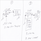
Glenn, observe A & B electrical circuits. [Two EMF
sources both drawing 15 amps through load resistor] In
drawing A there simply is .3 volts across Ri, which results
in 15 amps of current flow, .3/.020 =15.
Files Referenced:

iATN Members:
Login to read this message and participate Auto Repair Pros: Join iATN to read this message and others Vehicle Owners: Find a nearby iATN member to repair your vehicle 1 Replies Received (View Replies)1 Replies Received (Hide Replies) |
 1 Replies Received
 1 Replies Received
 Video
Video