Posted to Technical Discussion Forum on 6/25/2011
65 Replies
Hi all. I have followed with interest some of the posts in
the last year or so, where CAN based communication case
studies have been presented for our interest and discussion.
In particular, more recently James Avery posted a High Speed
GM LAN issue and as I observed the ensuing thread unfold, it
became apparent that there was plenty of interest in this
topic.
While CAN systems have been around for a long time, we have
seen CAN "C" brought into the forefront since the 2008 MY.
What I notice is that the case studies are great, but
participation is somewhat limited to a few "die hards" who
either understand the system function, failure and
diagnostics, or conversely, quite openly admit that they
lack knowledge of the CAN systems and yearn for more.
So, the purpose of my post is to contribute some numbers and
a few thoughts to the cause. While I no longer actively
wrench as a technician, I must also learn each new
technology and system as it is introduced, on a wider range
of vehicle systems than when I was a technician full-time.
Apprenticeship, vehicle manufacturer and dealership needs of
the shop and technicians, dictate that we train students in
specific areas and network communications is a clearly
defined apprenticeship topic in third level.
While my work may not quite assimilate your "real world"
experiences, it is my "real world", where not only installed
bugs, mishaps, damage and other problems happen to challenge
us along the way. During my week, there is some time set
aside without students present, for me to attend to
"Functions 3 to 8" in our collective agreement. This covers
a wide range of program maintenance needs, processing marks,
prepping labs and taking care of ensuring that everything is
up and running.
This particular Friday began with me scheduling marks
processing and prep work, but first I needed to move a few
vehicles around for the next series of activities. One car,
a 2009 Chevrolet Mailbu 2.4L, was sitting in the shop. That
needed to go outside, but it didn't crank. The dome lamps
and IP were lit with doors open and key on, exterior lamps
turned on, but nothing happend when the key was turned to
crank. Without getting sidetracked, there were a few other
systems that didn't function, such as the electric trunk
release, but all that I wanted at this point was to shift
the beast outside. I'm on my own, all alone with nobody with
me, so pushing is out.
Darn, I'd better fix it myself, methinks. Besides, this is a
bit more interesting than paperwork anyway. Work boots, and
PPE at the ready, what's the next step going to be? I know
where iATN's resident litigation consultant would have us
head, word by word, but GM created something known as
"Diagnostic Strategies" a few years ago, that provides GM
technicians with more diagnostic freedom to use their
knowledge, expertise and experience to either use some very
basic methods, or if a novice, to do the step by step dance.
I manage my novices closely enough to develop and install
some critical thinking skills and to understand that they
need to be able to manage their diagnostic skills and logic
within reasonable relams of the corporate process to be sure
to be paid. Once they have developed a wider range of
skills, their wings will be set free to soar, but for now
they're "clipped" to keep them from wandering too far from
the beaten path. Since I routinely lead students into
developing a logical diagnostic approach that may
assimilate, but not necessarily 100% duplicate the
manufacturer steps, based on needs and critical thinking
abilities, much of the stuff is ingrained in my "noggin."
Besides, I'm not on flat rate any longer and I am my only
audience, with the freedom to stray, wander and experiment
today, as I see fit.
So, let's gather a little info. What do I know of the
vehicle? It is a 2009 Malibu, donated to the program by GM
Canada, with a couple of scrapes/mild dents in the roof from
transit damage. It has performed flawlessly to date, used
for various topics this term from body electrical, network
communications, engine management and emissions. I don't
know and really don't care at this point, how it became
non-functional. I'm just a tech today with a broken car in
my work bay that needs to be fixed ASAP.
Now, you already know that as I write this, that the vehicle
may well be fixed and it is, but when I spent a minute or so
getting my diagnostic direction figured, it became apparent
that this may be useful in a post. To that end, I elected to
snap a few photos of scan data, DMM display values etc along
the way. Since taking photos of a DMM display with overhead
lights, trouble lights and other effect on camera angle, can
produce inconsistent quality photos, I snapped some photos
of the Fluke 87 V photo, but for clarity, created some text
boxes for better viewing on this wet Saturday afternoon.
So, what's the approach? Preliminaries, looked okayish and
while I might have tested every fuse in some random fashion
like many do, which simply wastes time, I'd rather home in
on what's working or not working in the major sense, to get
a better grasp. Besides, if get a schematic, it will show
the appropriate fuses and save a bunch of time not checking
those that don't need it.
While a few other things may or may not work, my primary
concern was a no crank, no click, no nothing response to
rotating the ignition key. Keep in mind, preliminaries
include visual, bulletins and more, depending on need, so
I'll keep that in mind. In my ex-role as a GM technician,
I'd use my "gut" feeling diagnostic approach to gain a sense
of direction, willing to trade 5 minutes or so using what I
know, versus following the "path of righteousness". No sense
of where to go, get on track with published info, not much
time lost.
Anyway, I know where the Diagnostic Starting Point et al,
will lead, so don't need to read it for the ten thousandth
time just yet. So, with Tech 2 and CANdi in hand, vehicle
info entered, the results of selecting "Vehicle Control
Systems" and waiting what seems like an eternity, renders
some modules with no communications and some with DTCs, on
Low Speed and High Speed GM LANs (HS & LS).
Ah, the path to take. Info is readily captured and kept in
mind for future needs. All this happened at one instant in
time, so in my mind, one problem is likely presenting
multiple DTCs and symptoms. I note that the BCM (on LS and
HS LAN) is present and showing 3 DTCs U2105 00, U 2106 00
and U2108 00, all were communication lost with other module
DTCs. There's also U 2109 00 (PSCM) and B2455 04 (VCIM)
listed.
So, we have problems communicating with various modules and
since the BCM and VCIM reside on both HS and LS LANs, some
stuff that may be useful later. Go ahead if you wish, check
bulletins and find the one that lists four of the five DTCs
and jump to conclusions that will not net a successful
diagnosis. I just log this stuff into long term memory in
case actual diagnostics don't yield a fix.
Now, I am already well aware from my background and
training, of the fact that some" big player" modules that
some of the DTCs represent only communicate on the HS LAN,
while some of the lower priority modules reside on the LS
LAN. Now, "Diagnostic Tragedies" as we so fondly call it,
allows us some freedom, but for those of you unfamiliar with
GM LAN schematics, you can use the menu path or a keyword
search to seek out some visual aids.
I didn't need to take this path, because I'm already homing
in on the HS LAN to do some basic tests, but then again, I'm
familiar enough to go ahead at this point. Still, looking at
the schematics can render some useful information such as
where to access the system for diagnostic tests beyond the
DLC.
Using the menu file path, head over to Power and Signal
Distribution, Data Communications, Schematics and Routing
Diagrams, Data Schematics, to arrive at Power, Ground and
Serial Data, where HS LAN is available with or without HP7
(hybrid) and LS LAN is also listed. This one is not equipped
with HP7. A quick review of both LAN schematics and noting
connector locations may be useful while here. Clicking on
the "LOC" button on a schematic (not available once in the
magnified view), will net the Master Electrical Component
page, where all components, connectors and harness routing
diagrams should be located.
If you want to have both windows, when clicking on the LOC
button, use the right click, open in a new window " method.
Real world, I rarely would bother. If I have an interesting
window open, I print it and take it to the vehicle.
If I already know the connector ID, I don't waste time with
file paths. Keywording "Master" from any search box and
dragging the slider rapidly to the very bottom of the page
will net "Master Electrical Component List" at or just above
the very bottom. The path above is for you if you wish, but
based on my knowledge, I'm going to do some quick tests at
the DLC.
Since the BCM is online, but nothing else, I expect that
voltages on the HS LAN should be as expected. I did make one
notation when I used the schematic, to aid my testing and
that was the location of the two 120 ohm termination
resistors in the HS LAN circuit. One is in the BCM which is
one stop downstream from the DLC and the second is internal
to the ECM, which is at the far end of the system, not
communicating.
This is the value obtained [2009 Chevrolet Malibu LS,
ECM/Inputs/Outputs Drawing]
That makes me happy, since if the resistance is as I
expected for a system with a data line problem that I
predicted from scan data and system funcitonality, I'm
probably looking for a simple open in the circuit. Don't
forget though, any time you make resistance measurements,
the system should be powered down for the values to make
sense. I caught a couple of students last week, diagnosing
an '08 Aveo CKP failure, measuring a ground circuit with the
ignition on, DRL (headlamps) shining brightly. They were
wondering while their measure valued was a really high ohms
value, but did net the same result on another ground. I just
happened to beat them to the ignition switch! VBG.
To get a mental picture, this HS LAN begins with the DLC and
strings modules along one after another and culminates at
the ECM. Two wires (Bus + and Bus -) enter and leave each
module. Looking at the schematics with the choices of RPO
applications can give you a headache and a couple of modules
are hung off the side of the chain and also have LS LAN
communications. If you need, it can be simpler to draw a
block diagram.
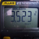
In this case I suspected that I would find around 120ohms
resistance when I measure the HS LAN across Bus Hi and Bus
Lo terminals 6 and 14 and net 121 ohms. If functioning as
designed, the value should be close to 60 ohms Don't forget
though, modules/networks need three things to function,
power, ground and a healthy data line. I have a scan tool
that functions, BCM is active and my focus is on physical HS
LAN Data Bus wiring.
Nothing beyond the BCM is communicating on the HS LAN. The
BCM is "conveniently" located in the centre console, where
each side panel is released by gently pulling to release the
fastener clips and Velcro. Access is pretty simple. I don't
look too deeply, but the BCM connections appear to not have
been disturbed by student hands, wiring all seems to be in
place securely.
Next stop along the trail is connector X206, sorry forgot to
snap a pic of these locations. It is very conveniently
located behind the removable access panel at the left end of
the dash, with the driver's door opened. Yippee, pick me,
pick me, I found it, stumbled right onto a problem!!! There
is a lever lock style connector that also has locking tabs,
but it is not fully seated. I'm not so sure that the
terminals can even make connection properly unless the lever
mechanism is snapped home, but I'm a "happy camper" (or will
be if this is the only thing I find wrong). I'll investigate
later whether this is a student installed bug or whatever,
but for now, I just want the vehicle out of the shop, so
that I can complete some paperwork and prep for next week.
With the ignition off, I pull the connector halves apart and
inspect for anything that might prevent them from proper
intercourse and find nothing. All terminals of this hybrid
(two sizes of terminals in one connector body) are fine and
undamaged. With the connector reconnected, the engine now
cranks and runs fine.
So, since I mentioned that I'd record some HS LAN
measurements for reference, I will disclose the values
measured from the DLC, prior to me chasing down the open
circuit. When testing the HS LAN, there are some very basic
tests to be completed and not all are necessary to complete
the diagnosis (See Diagnostic Strategies) if the fault is
found. The status of the HS LAN can be checked using a DMM
or a DSO if you so wish, but it needs to be fast enough to
capture the data accurately enough for comparison to specs.
Throw away that cheapo $25 meter and ante up for a
professional DMM. GM recommends the Fluke 87 V and since I
have one, I used it to record the following measurements. I
did also use a Fluke 87 III, which while a capable meter and
did capture reasonably accurate results, was just a skip
behind the 87 and I did have to retake a couple of
measurements. I noticed that the high and low values on peak
min max were not quite as high or low when using the 87 III,
but they were still valid enough to make sense.
What's to be measured? Well, the simplest is to check the
resistance across HS LAN terminals 6 and 14 at the DLC.
Here's the measurement after the system has been repaired
[2009 Chevrolet Malibu LS, ECM/Inputs/Outputs Photo]
On a healthy HS LAN, this should be approximately 60 ohms,
but on a system where the module with the second terminating
resistor is missing, 120 ohms will be measured if the data
Bus is open. Remember, we still need power, ground, a
healthy pair of data lines and modules for everything to
function normally.
Here is the resistance check value again, of this Malibu
with no communication on the HS LAN data lines beyond the
BCM. [2009 Chevrolet Malibu LS, ECM/Inputs/Outputs
Drawing]
Additionally, there is a photo of the external termination
resistor from a current model GMT900 Chevy/GMC pickup truck,
showing the same value as achieved on the Malibu. [2008
Chevrolet Silverado 1500 LT, ECM/Inputs/Outputs Photo]
This resistor resides on the left frame rail close to the
spare tire.
The resistors provide a load on the circuit and also are
very useful diagnostic aids as James, Bob and others have
already eluded. I would suggest that if you wish to learn a
little about GM HS LAN diagnosis, that these trucks are
plentiful and easy to access. I'll let you be creative and
learn for yourself, what happens when you remove this
resistor and leave the circuit open or jumper the lines
together, or ground either one or both. This is your
homework project! You will learn when you do it for
yourself.
Measure voltage using a high quality meter capable of making
the following measurements: Measure terminals 6 (Bus Hi) to
(5 Ground) with a DMM on volts. [2009 Chevrolet Malibu
LS, ECM/Inputs/Outputs Photo] Note the measurement is in
basic DC volts and also autoranging. it was simply turned on
with voltage selected set up to make basic voltage
measurements, but regardless of whether a fixed range is
selected the meter just isn't fast enough for testing serial
data communication circuits accurately this way.
You can try the Fluke 87 variants on min max, where the
meter is not auto ranging, but will need to depress the
"speaker" button to select Peak Min Max for the reading to
be accurate enough. Since the 87 V is four times faster at
250 microseconds in peak min max, as opposed to the 87 III
mS capability, I'm going to use the 87 V for these
measurements.
What do we know about the GM LAN? It utilizes a twisted pair
of data communication lines aka Data Busses. They are
stacked at the DLC at terminals 6 and 14, which are directly
above and below one another, since its hard to have twisted
pairs anyplace but next to one another. Here's the DLC
terminal pin assignment [2009 Chevrolet Malibu LS,
ECM/Inputs/Outputs Photo]
HS is at terminal #6 and the wire is tan with a brown
tracer. LS is at terminal 14 and the wire is tan in colour.
When we make measurements from terminal 6 to 5 (ground), we
expect to find a nominal 2.5 volts when measured on a DCV
scale. In reality, the value for terminal 6 will be a few
points of a volt higher than for terminal 14. Remember, this
is when performing a basic voltage measurement.
When we select the peak min max function, the values will be
quite different. E.g. we should see approximately 3.5V MAX
measured at 6 to 5 and 2.4v MIN. This verifies our
understanding that HS Bus HI moves up approximately 1 volt
during activity.
Similarly, when making the same peak min max measurements
from terminal 14 - 5, we will see approximately 2.5v MAX and
1.5v MIN values displayed if all is well, with the same 1
volt differential from rest. If voltages do not fall into
these ranges, problems exist that require diagnosis, such as
any short to voltage, open or ground condition will cause.
When measuring voltage across terminals 6-14, we will
measure somewhere in the millivolt range between 50 and 500
millivolts. This one measured [2009 Chevrolet Malibu LS,
ECM/Inputs/Outputs Drawing]
However, when we repeat the same measurements using the peak
min max feature of the Fluke 87 V, the results will be in
the neighbourhood of 2.4V MAX and 0.25V MIN. Here are the
actual measurements [2009 Chevrolet Malibu LS,
ECM/Inputs/Outputs Drawing] and [55184] This reading is
simply the differential voltage on BUS and the only way to
see it is using a meter or scope that is capable of
recording accurately.
I happened to have a couple of logic probes handy along with
a few other "quick and dirty" tools for basic system quick
checks, but prefer the peak min max on the DMM because the
numbers mean more to me. "Scopeaholics" can capture very
accurate waveforms and analyze them to "death." Personally,
I use the "KISS" approach when diagnosing vehicles and use
the most basic tools first. If I am not satisfied or looking
for something beyond, I have scopes close by for back up.
Bear in mind that some vehicles utilize more than one HS
LAN, simply to limitations of the CAN BUS. In those cases,
we might find a chassis expansion bus or hybrid expansion
bus, piggy-backed to the system, much like you can add an
electrical subpanel to your home electrical system.
So, when James and other post voltages, we need to
understand or at least ask how the measurement was made, if
we are to be able to compare their measurements to good
known values. If the method of recording the voltages isn't
good enough, the numbers won't provide proper diagnostic
value.
Here are actual photos and a series of text boxes showing
Volts and Ohms Basic tests follow:
KOEO Terminal 6-5 = [2009 Chevrolet Malibu LS,
ECM/Inputs/Outputs Photo]
KOEO Terminal 6-5 peak min max -- MIN = [2009 Chevrolet
Malibu LS, ECM/Inputs/Outputs Drawing] KOEO Terminal 6-5
peak min max - MAX = [2009 Chevrolet Malibu LS,
ECM/Inputs/Outputs Drawing]
KOEO Terminal 14-5 = [2009 Chevrolet Malibu LS,
ECM/Inputs/Outputs Drawing] KOEO Terminal 14-5 peak min
max -- MAX = [2009 Chevrolet Malibu LS,
ECM/Inputs/Outputs Drawing] KOEO Terminal 14-5 peak min
max -- MIN = [2009 Chevrolet Malibu LS,
ECM/Inputs/Outputs Drawing]
KOEO Terminal 6-14 = 0.314v DC [2009 Chevrolet Malibu
LS, ECM/Inputs/Outputs Drawing] KOEO Terminal 6-14 peak
min max- MAX = [2009 Chevrolet Malibu LS,
ECM/Inputs/Outputs Drawing] KOEO Terminal 6-14 peak min
max -- MIN = [2009 Chevrolet Malibu LS,
ECM/Inputs/Outputs Drawing]
Powered down Terminal 6-14 ohms ( in spec) = [2009
Chevrolet Malibu LS, ECM/Inputs/Outputs Drawing] Powered
down Terminal 6-14 ohms (out of spec) = [2009 Chevrolet
Malibu LS, ECM/Inputs/Outputs Drawing]
Here's a few of the other Fluke 87 V photos. {File55169]
[2009 Chevrolet Malibu LS, ECM/Inputs/Outputs Photo]
[2009 Chevrolet Malibu LS, ECM/Inputs/Outputs Photo]
[2009 Chevrolet Malibu LS, ECM/Inputs/Outputs Photo]
The basics of the GM HS LAN is that at rest, the voltages
are close to 2.5v DC on both Bus Hi and Bus Lo and
considered to be "recessive transmitted logic", while the
Bus + (HI) will climb approximately 1 volt and the Bus -
(LO) will drop approximately 1 volt in the "dominant" state.
In the recessive state there is close to 0 volts
differential, but in the dominant state, the voltage
differential is approximately 2 volts.
The BCM is the Power Mode Master for wake up of HS LAN
modules. If the modules are present on the list when
scanned, but receive no wake up signal, they will not become
active.
If you take the number presented here and do the math, the
measured values support the theory behind how the system
functions.
So, do we need to run off to investigate service information
every time we are faced with a high speed GM LAN failure? It
Depends on our abilities and needs. If we can remember some
rest voltages and peak min max values of up and down 1 volt
for a 2 volt differential, along with what 60 ohms and 120
ohms represent, or anything in between, we may only need to
ustilze information for connector access and the basic LAN
layout, to get our heads around where the LAN may be broken.
You can pretty much guess what the ohm value will be if
modules downstream are lost due to a data line failure.
Regards,
Martin from British Columbia


 65 Replies Received
 65 Replies Received
 Vehicle Data