Gauging axle drive pinion depth. What do you use?
Posted to Technical Discussion Forum on 11/15/2009
22 Replies
A recent post discussing multiple premature rear axle
failures, prompted me to put this post together. Does your
shop take axle repairs seriously enough to provide the
necessary tooling to achieve accurate pinion depth setting
without trial and error or guess and by golly methods? Do
you have to make do? Do you have alternate pinion shim
selection tools that you are willing to demonstrate or share
here? I have seen and used others, some good, some not so
good. Gauge tools come in various shapes and sizes.
There are several methods to achieving successful pinion
depth, given the work place circumstances. If the same axle
housing is being used on an integral style axle housing,
technicians will often get away with re-using the original
shim.
What happens when your parts department hands you a brand
new or used axle housing for you to build? Yes, I am well
aware that there's a general starting shim depending on axle
ratios, but why not blow the dust off that pinion depth
gauging kit and give it a whirl?
This post will outline some of the tools and processes to
achieve the pinion depth setting for a GM American Axle
Manufacturing (AAM) 8.625" rear axle as used in many light
duty GM pickup trucks. Set up is similar for other integral
housing GM corporate and AAM axles. 10.5" corporate axles
use a removable pinion carrier which is shimmed between the
housing to achieve pinion depth. That will not be covered
here.
Danas are also a different beast which require a slightly
different location for shimming and use shims rather than
collapsible spacers to achieve pinion rotational torque, so
they will not be referenced in this post. GM uses nominal
pinions, no +/- numbers to incorporate as in Danas of the
past and other brands.
Along the way, some of the tools as used in GM dealerships
will be depicted. You will likely have alternate tools and
methods and that's fine by me. The object isn't to proclaim
that the OEM tools and methods are the only way, it's simply
to share effective information with interested parties who
may benefit from discussion.
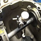
During axle disassembly the time will come to remove the
companion flange (yoke) from the drive pinion. This tool
[2007 Chevrolet Silverado 1500 Classic LT, Not Applicable
photo] makes light work of holding the flange still while
removing the pinion nut and washer. The forcing screw is
then installed and the flange can be drawn from the pinion
with a 1" socket and driving method of your choice. Here's
the tool assembled on the flange following removal from the
pinion [2007 Chevrolet Silverado 1500 Classic LT, Not
Applicable photo].
A driver handle threads onto the drive pinion and the pinion
is removed from the bearings and the collapsible spacer and
rear pinion bearing removed. Shown is the rear pinion
bearing removal tool for later AAM axles. [2007 Chevrolet
Silverado 1500 Classic LT, Not Applicable photo] This can
then be mounted in a bearing splitter and pressed from the
drive pinion.
The later design bearing cannot be removed using a bearing
splitter alone as in previous designs. Both the early and
later dsign bearings will physically fit into the axle
housing and onto the drive pinion, but cup and cones are not
interchangeable due to different internal dimensions between
the cup and cone.
To save knuckles and minimize the chance of damage to the
housing, I use this [2007 Chevrolet Silverado 1500
Classic LT, Not Applicable photo] MAC Tools PB37L driver
to remove front and rear pinion bearing cups from the
housing. It is approximately 18" overall length and does the
job very well. Contrary to popular belief, the words "brass"
and "bearings" should not be used in the same sentence.
Brass can easily chip or transfer and embed in the surface
of other components.
Always thoroughly clean and inspect the pinion bearing bores
and shoulders for nicks and burrs after bearing removal. Use
the end of a file or gasket scraper to remove any burrs,
otherwise the replacement bearing cup may not fully seat in
the bore.
Lubricate the bearing bores and outside of the pinion
bearing cups, then install using the appropriate bearing
drivers. Ensure the cups are fully seated. If the rear
bearing is not fully seated, you might as well guess the
required pinion shim! In these axles the shim fits between
the drive pinion head and rear bearing.
Here's the GM spec pinion depth gauging kit, which has
adaptors and two arbors which fit the needs of 6.5" - 9.5"
GM axles. [2007 Chevrolet Silverado 1500 Classic LT, Not
Applicable photo] and instructions/application guide
[2007 Chevrolet Silverado 1500 Classic LT, Not Applicable
photo]. Here's a better view of some of the adaptors and
gauge plates [2007 Chevrolet Silverado 1500 Classic LT,
Not Applicable photo] and [2007 Chevrolet Silverado
1500 Classic LT, Not Applicable photo]. Here is how the
selected adaptors and gauge plate will fit in place of the
drive pinion [2007 Chevrolet Silverado 1500 Classic LT,
Not Applicable photo].
With the gauge plate assembled in the housing in lubricated
bearings and the specified rotational torque achieved
[2007 Chevrolet Silverado 1500 Classic LT, Not Applicable
photo], the 8.5" gauge block will be utilized in this
instance. 8.5" ring diameters were updated to 8.625" many
years ago, as were 7.5" to 7.625" ring gears, but the gauge
plates are the same. [2007 Chevrolet Silverado 1500
Classic LT, Not Applicable photo] shows the gauge arbor,
discs and dial indicator assembled in the axle housing. With
the side bearing caps installed and torqued to specs, the
arbor should rotate freely. A misaligned bearing bore can
quickly be identified using the arbor.
This is my well-used personal kit for axle set up with a few
extras. [2007 Chevrolet Silverado 1500 Classic LT, Not
Applicable photo]
With the dial indicator in alignment with the head of the
spring loaded arbor plunger and the plunge tip placed on the
gauge plate, slide the dial indicator down the pillar until
approximately 3/4 revolution of gauge travel is noted after
the indicator contacts the arbor plunger.
Rotate the arbor, while maintaining plunger contact with the
gauge plate and note the location of highest upward
deflection of the arbor plunger. Zero the dial indicator at
this point [2007 Chevrolet Silverado 1500 Classic LT,
Not Applicable photo]. Recheck and make any re-adjustment
to ensure that maximum upwards movement indicates zero."
Rotate the arbor until the plunger moves completely off the
gauge plate surface. Read the measurement on the dial
indicator. [2007 Chevrolet Silverado 1500 Classic LT,
Not Applicable photo] In this case the original shim
actually measured 0.0375" with a micrometer and is very
close to the gauged shim value on the dial indicator.
With the shim and drive pinion rear bearing lubricated and
installed, assemble the pinion into the axle housing,
install a new collapsible spacer (crush sleeve) lubricated
front pinion bearing, pinion seal and companion flange with
sealant on flange splines. Install washer, a new pinion nut
and tighten nut to achieved specified rotational torque.
Rotating the pinion and a light "love tap" will seat the
pinion bearing rollers which have a tendency to skew
slightly during the tightening process. Use your preference
of brute force or torque multiplier [2007 Chevrolet
Silverado 1500 Classic LT, Not Applicable photo] to
collapse the spacer. Be very careful to advance slowly in
small increments when close to achieving spec torque which
noted during rotation of the pinion.
With the pinion shim selected and installed, all that
remains is to reassemble the gear case into the housing, set
backlash and side bearing preload, then take a contact
pattern. There's nothing to that part of the process, or is
there??? How is shim selection achieved to obtain backlash
and side bearing preload measured? Maybe next time.
For those who have never experienced set up of rear axles, I
hope you found this process interesting. Other methods and
tools will differ. Feel to share your methods.
Regards.
Martin from British Columbia


 22 Replies Received
 22 Replies Received