Posted to Technical Tips Forum on 10/10/2014
24 Replies
This is intended for those who are interested in CAN Bus
exploits.
Coming soon (possibly next week) to North American GM
dealerships near you, is the GM "Data Bus Diagnostic Tool".
I had the opportunity to download the program via TIS2Web
this week and try it out on a couple of vehicles. The
vehicle of choice for this post is a 2014 Chevrolet
Silverado 1500 4WD truck, into which faults were inserted to
view the program in action. However, the vehicle itself is
not the real focus, but the Data Bus Diagnostic Tool (DBDT)
may be of interest.
The main intent of the tool is to assist technicians in
diagnostic direction and proficiency.
Let's begin by identifying how the program is started once
downloaded. Data Bus Diagnostic Tool shows the main
features of the home screen. Not shown is a single cursor.
Rather than attempt to explain all of the features (and to
be quite honest, I have not had time to explore the program
extensively since my free time is a premium), what follows
will be a basic program overview as an introduction.
Once downloaded via TIS2Web, the program is accessed via a
desktop shortcut. When the window opens, a very simple
screen is displayed with some selectable tabs across the
header, selectable bus type with baud type identified and a
row of control buttons across the bottom of the screen.
Nothing will happen unless the green power button is
clicked, at which point the button changes to a red X used
to close the program.
The Data Bus Diagnostic Tool uses the MDI as the interface,
so if GDS 2 is hogging the MDI, it must be disconnected to
allow the DBDT to identify and utilize the MDI, which will
be identified. No MDI
It is no create surprise that the speaker button allows the
program to feedback an audible tone that sounds quite
similar to the screech of a logic probe when used to test a
data bus. There is an option to have the beeper tone present
during the presence of a bus fault or when the bus is
functioning normally. To the right of the display area tool
bar, is the familiar system voltage sign. Note that the KOEO
voltages were low; only because the truck has sat unused
since early June, save for being moved once in a while.
The photos are annotated to be fairly self-explanatory, but
if the MDI is not connected, or is assigned to another
program as aforementioned, it must be connected to the DBDT.
There is an option to select devices, so I have no idea
whether alternatives to the MDI will work, since I have not
had the chance to try any.
This photo demonstrates the program in action with the
vehicle KOEO. Normal Bus Function Normal HS GM LAN
(CAN) voltages
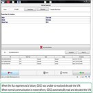
In subsequent screens a simple fault will be introduced, to
see how quickly the program reacts to a failure. The various
states and time stamps from normal to failures and back to
normal function on the bus will be displayed. Bus
Detected State
The fault was introduced into the circuit at the under hood
fuse box, by removing fuse # 57, which is an ATC 3-Leg Micro
Blade fuse, which happens to feed both the ECM and TCM. As
expected and can be noted in this photo, Also noted in the
next photo is the change in the bus signal. HS LAN Bus
fuse 57 reinstalled ECM and TCM back on line
This was done a few times in succession with consistent
results during both KOEO and KOER. Turning the ignition off,
the bus voltage began stepping down and when the key was
turned back on, the voltage immediately rose to normal.
HS LAN going to sleep
Now, I'm not overly worried about "bricking" a module, since
we have only experienced a single module failure in many
years. However, the next photo A Failure depicts a real
failure on the bus. While viewing the effect of the fuse
removal and reinsertion, someone happened to open the
driver's door and the Bus Hi voltage dropped to 0 volts, as
can be seen in here in the Measurement screen Bus Hi at
0 volts and is verified in the Detected State screen.
Bus State
All module communication with the tool was lost, while the
truck still ran, although when the rpm was raised, throttle
control resulted in unstable flaring.
The bus Hi voltage moved from an initially unstable state to
0 volts from this time until proper function was restored.
Powering down the DBDT and once connected, GDS 2 would no
longer read or decode the VINas it would normally in this
photo. GDS 2 When entering the VIN # manually, no
communication was the result. Letting the truck go to sleep
had no effect and neither did disconnecting the battery and
connecting the cables together. I was pretty sure that the
issue was in the ECM, but I had to head home for the day,
since this was all done well on my free time.
At 4:45 am this morning I disconnected the ECM [2014
Chevrolet Silverado 1500 LT, ECM/Inputs/Outputs Photo] and
waited a few minutes, then reconnected the three ECM
connectors. Subsequently, normal data bus function was
restored as was viewed on the DBDT. Scanning the system with
GDS 2, resulted in DTCs stored in many modules as expected
Bus function restored, GDS 2 display , which were then
cleared, as shown here. DTCs cleared
Martin from British Columbia


 24 Replies Received
 24 Replies Received