|
A New Year
Scott Brown
Once again, we have found some excellent material shared on iATN last quarter! We've noticed a technique starting to gain in popularity -- "Engine Pumping Analysis" is featured in a couple of the articles below. With many of today's engine configurations, technicians find it quite difficult to gain access to spark plugs in order to perform simple compression tests. With a lab scope and a vacuum/pressure transducer, a tech can now perform some interesting tests producing valuable, diagnostic information without the removal of any spark plugs. Additionally, you'll find an article covering broken spark plug removal on V8 Fords, a nice article on Differential Service and a nice tip on Wheel Alignments.
We recently rolled out several new features and improvements, including the ability to upload multiple files at once, with a stream-lined procedure to make sharing your waveforms and other files very easy. In addition, the File Uploader will allow for larger file sizes and more formats.
We've made search engine improvements in the Forum Archives and the Waveform/File library, now providing a "live count" of search results before you even leave the search form, just like in the FIX Database. Now you can "tweak" your search criteria in order to obtain a manageable count before proceeding to the results page.
Also added: new larger image previews for the embedded images found in forum messages, allowing you to see fine detail in the images, and avoid having to leave the message in most cases. The web forum posting page has been modified so that by default you will see your personal file library images at the bottom of the screen, which makes inserting them into your forum message a breeze!
At the beginning of 2010, we hit a new milestone, with our active membership now exceeding 70,000 members from 157 countries. This takes the combined experience level of the membership to 1.6 million years!
We're glad your taking time to read the iATN Review and hope you enjoy it. Please feel free to forward it to your co-workers and other automotive professionals!
Regards,

Scott Brown
iATN President

04 Ford F-150 5.4 Spark Plug Removal
Technical Tips Forum
Thomas from South Carolina
Most iATN members are aware of the Ford 4.6, 5.4 and 6.0 spark plug breaking issue. Having the same frustration, even when following the Ford service bulletin I have added some steps that seem to help aid in the removal of the plugs without breaking.
The Ford service bulletin 08-7-6 which updates 08-1-9 is of some value, as I follow those steps after doing some prep work.
This is what I do.
1: Explain to Owner that this is a long process and they will need to be without their vehicle for two maybe three days. I try to convince owners not to exceed 80,000 miles for spark plug replacement interval.
2: The first morning run engine to operating temperature and remove the crankcase vent hose, the small one on the passenger side of the air cleaner housing.
3: Either use a pedal jack or have helper hold throttle to 2,000 rpm. Using suction spray nozzle, spray GM upper engine and fuel injector cleaner #88861802, into the vent port on air cleaner housing. After 3 ounces have been used and while still spraying have helper shut engine off. (throttle still held open)
4: After sitting for 1 hour repeat step #3 after running engine to operating temperature.
5: Before closing on day 1, Repeat step #3 again after running engine to operating temperature. Place vehicle in the bay in which you intend to work. This allows engine to cool overnight to ambient temperature as necessary.
6: Day 2 start plug removal process.
I also add the following steps to the next phase of plug removal.
1: Break the plugs 1/8 turn only, then fill to hex of pug with penetrating oil. I use PB blaster. After 1/2 hour tighten plug and loosen 1/4 to 1/2 turn be sure penetrating oil is still to the hex of the plug. After 1 hour, tighten plugs and then work them out alternating loosening and tightening.
I have found that while removing the plugs if they squeak, they come out intact. No squeak and they are broken.
Using these additional steps I have been able to remove plugs with no more that 2 breaking. Some 1 and others none. I may be doing more work than necessary but it is a pain to remove the broken tips.
Speaking of removing broken tips, the tool that I have found to work the best is the Lisle #65600.
I listed this as 04 F150 because this is the vehicle that I just finished. #6 broke, all others came out intact. This applies to other Ford vehicles.
Hope this helps make it easier for some Members.
Gauging Axle Drive Pinion Depth. What Do You Use?
Technical Discussion Forum
Martin from British Columbia
A recent post discussing multiple premature rear axle failures, prompted me to put this post together. Does your shop take axle repairs seriously enough to provide the necessary tooling to achieve accurate pinion depth setting without trial and error or guess and by golly methods? Do you have to make do? Do you have alternate pinion shim selection tools that you are willing to demonstrate or share here? I have seen and used others, some good, some not so good. Gauge tools come in various shapes and sizes.
There are several methods to achieving successful pinion depth, given the work place circumstances. If the same axle housing is being used on an integral style axle housing, technicians will often get away with re-using the original shim.
What happens when your parts department hands you a brand new or used axle housing for you to build? Yes, I am well aware that there's a general starting shim depending on axle ratios, but why not blow the dust off that pinion depth gauging kit and give it a whirl?
This post will outline some of the tools and processes to achieve the pinion depth setting for a GM American Axle Manufacturing (AAM) 8.625" rear axle as used in many light duty GM pickup trucks. Set up is similar for other integral housing GM corporate and AAM axles. 10.5" corporate axles use a removable pinion carrier which is shimmed between the housing to achieve pinion depth. That will not be covered here.
Danas are also a different beast which require a slightly different location for shimming and use shims rather than collapsible spacers to achieve pinion rotational torque, so they will not be referenced in this post. GM uses nominal pinions, no +/- numbers to incorporate as in Danas of the past and other brands.
Along the way, some of the tools as used in GM dealerships will be depicted. You will likely have alternate tools and methods and that's fine by me. The object isn't to proclaim that the OEM tools and methods are the only way, it's simply to share effective information with interested parties who may benefit from discussion.
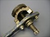
During axle disassembly the time will come to remove the companion flange (yoke) from the drive pinion. This tool [2007 Chevrolet Silverado 1500 Classic LT, Not Applicable photo] makes light work of holding the flange still while removing the pinion nut and washer. The forcing screw is then installed and the flange can be drawn from the pinion with a 1" socket and driving method of your choice. Here's the tool assembled on the flange following removal from the pinion [2007 Chevrolet Silverado 1500 Classic LT, Not Applicable photo].
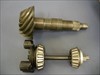
A driver handle threads onto the drive pinion and the pinion is removed from the bearings and the collapsible spacer and rear pinion bearing removed. Shown is the rear pinion bearing removal tool for later AAM axles. [2007 Chevrolet Silverado 1500 Classic LT, Not Applicable photo] This can then be mounted in a bearing splitter and pressed from the drive pinion.
The later design bearing cannot be removed using a bearing splitter alone as in previous designs. Both the early and later dsign bearings will physically fit into the axle housing and onto the drive pinion, but cup and cones are not interchangeable due to different internal dimensions between the cup and cone.
To save knuckles and minimize the chance of damage to the housing, I use this [2007 Chevrolet Silverado 1500 Classic LT, Not Applicable photo] MAC Tools PB37L driver to remove front and rear pinion bearing cups from the housing. It is approximately 18" overall length and does the job very well. Contrary to popular belief, the words "brass" and "bearings" should not be used in the same sentence. Brass can easily chip or transfer and embed in the surface of other components.
Always thoroughly clean and inspect the pinion bearing bores and shoulders for nicks and burrs after bearing removal. Use the end of a file or gasket scraper to remove any burrs, otherwise the replacement bearing cup may not fully seat in the bore.
Lubricate the bearing bores and outside of the pinion bearing cups, then install using the appropriate bearing drivers. Ensure the cups are fully seated. If the rear bearing is not fully seated, you might as well guess the required pinion shim! In these axles the shim fits between the drive pinion head and rear bearing.
Here's the GM spec pinion depth gauging kit, which has adaptors and two arbors which fit the needs of 6.5" - 9.5" GM axles. [2007 Chevrolet Silverado 1500 Classic LT, Not Applicable photo] and instructions/application guide [2007 Chevrolet Silverado 1500 Classic LT, Not Applicable photo]. Here's a better view of some of the adaptors and gauge plates [2007 Chevrolet Silverado 1500 Classic LT, Not Applicable photo] and [2007 Chevrolet Silverado 1500 Classic LT, Not Applicable photo]. Here is how the selected adaptors and gauge plate will fit in place of the drive pinion [2007 Chevrolet Silverado 1500 Classic LT, Not Applicable photo].
With the gauge plate assembled in the housing in lubricated bearings and the specified rotational torque achieved [2007 Chevrolet Silverado 1500 Classic LT, Not Applicable photo], the 8.5" gauge block will be utilized in this instance. 8.5" ring diameters were updated to 8.625" many years ago, as were 7.5" to 7.625" ring gears, but the gauge plates are the same. [2007 Chevrolet Silverado 1500 Classic LT, Not Applicable photo] shows the gauge arbor, discs and dial indicator assembled in the axle housing. With the side bearing caps installed and torqued to specs, the arbor should rotate freely. A misaligned bearing bore can quickly be identified using the arbor.
This is my well-used personal kit for axle set up with a few extras. [2007 Chevrolet Silverado 1500 Classic LT, Not Applicable photo]
With the dial indicator in alignment with the head of the spring loaded arbor plunger and the plunge tip placed on the gauge plate, slide the dial indicator down the pillar until approximately 3/4 revolution of gauge travel is noted after the indicator contacts the arbor plunger.
Rotate the arbor, while maintaining plunger contact with the gauge plate and note the location of highest upward deflection of the arbor plunger. Zero the dial indicator at this point [2007 Chevrolet Silverado 1500 Classic LT, Not Applicable photo]. Recheck and make any re-adjustment to ensure that maximum upwards movement indicates zero."
Rotate the arbor until the plunger moves completely off the gauge plate surface. Read the measurement on the dial indicator. [2007 Chevrolet Silverado 1500 Classic LT, Not Applicable photo] In this case the original shim actually measured 0.0375" with a micrometer and is very close to the gauged shim value on the dial indicator.
With the shim and drive pinion rear bearing lubricated and installed, assemble the pinion into the axle housing, install a new collapsible spacer (crush sleeve) lubricated front pinion bearing, pinion seal and companion flange with sealant on flange splines. Install washer, a new pinion nut and tighten nut to achieved specified rotational torque. Rotating the pinion and a light "love tap" will seat the pinion bearing rollers which have a tendency to skew slightly during the tightening process. Use your preference of brute force or torque multiplier [2007 Chevrolet Silverado 1500 Classic LT, Not Applicable photo] to collapse the spacer. Be very careful to advance slowly in small increments when close to achieving spec torque which noted during rotation of the pinion.
With the pinion shim selected and installed, all that remains is to reassemble the gear case into the housing, set backlash and side bearing preload, then take a contact pattern. There's nothing to that part of the process, or is there??? How is shim selection achieved to obtain backlash and side bearing preload measured? Maybe next time.
For those who have never experienced set up of rear axles, I hope you found this process interesting. Other methods and tools will differ. Feel to share your methods.
Pressure Transducer Waveforms
Technical Tips Forum
Kevin from Manitoba
1996 Chevy S-10 2.2 Liter engine. Customer says he requires a new engine. He said he heard a knocking noise and eventually it got to the point it will not start. He asks me to either install a used Engine or get this engine running so he can trade it in.
So I have the vehicle towed in and get in the vehicle and crank it over.Its turning over real quick and sounds like there is no compression.(The kind of sound you hear when your cranking over an engine with a timing belt failure)A quick note* on the scanner a code showed up for knock sensor. I get out of the vehicle and I can smell the fresh scent of raw fuel in the air,a visual showed no signs of rods hanging out the side of the block or pan. I decide its time to check some basics with the scope and a pressure transducer, I remove the spark plug on cylinder #1 and I can see the gap is about twice the size of what it should be.
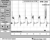
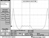
I install a 500 PSI snap-on pressure transducer into cylinder #1 and I hook up a secondary lead from the scope and test leads to cam and crank sensors. I crank the vehicle over and this is the waveforms patterns I get.[1996 Chevrolet S10, Engine/Propulsion waveform] We can see from that pattern we have secondary ignition firing, a cam and crank signal (out of sync compared to [1996 Chevrolet Cavalier, CKP Sensor, CMP Sensor Waveform] ) and a pressure transducer waveform that has an unrecognizable signature pattern. With the fact its obviously out of time, I then decide to remove the valve cover and loosen off each rocker and examine the valves with my borescope (no valves appear to be bent from what I could see with the borescope)I decide I should do a leak down test anyways to verify no valves were bent.(This test indicted a minimal leak down rate on all cylinder) "So good no valves are bent" I then decide its time to remove the timing chain cover and this is what I see [1996 Chevrolet S10, Engine/Propulsion photo]. Wow approx 9 teeth out. I install a new timing chain and tensioner/oil change and button the front cover back up. I then take another capture of this vehicle cranking over [1996 Chevrolet S10, Engine/Propulsion waveform] Well that looks better its now in sync.Now lets see if this thing starts [1996 Chevrolet S10, Engine/Propulsion waveform]Hey its running. Now since I havent buttoned up the valve cover yet I decide to take some running compression transducer waveforms with different scenario's, I loosen off different rocker combinations and capture the corresponding waveforms [1996 Chevrolet S10, Engine/Propulsion waveform] Some interesting patterns and pressure's displayed. I then check each cylinder separately and note the captures [1996 Chevrolet S10, Engine/Propulsion waveform] and a closer look at cylinder #1 [1996 Chevrolet S10, Engine/Propulsion waveform] I finish putting it all back together,installed new spark plugs cleared the code and started it up running on all 4 cylinders, It ran very nicely [1996 Chevrolet S10, Ignition scandata] And the Happy customer was very surprised he didnt need an engine.
A little note, when using the 500 PSI snap-on Pressure transducers they will give you a fairly good representation of the running/cranking compression waveform pattern itself, However the pressure Scale will be off to some duration because of the inability to maintain the proper scaling. When examining the running pressure waveforms with a good sealing engine generally you should note where the exhaust pattern peaks and this should theoretically cross over the 0 PSI line to confirm the exhaust is actually escaping the engine as shown here [2002 Ford Focus, ECM/Inputs/Outputs waveform]
Hopefully this helps somefolks out.
Alignment by the Numbers
Technical Tips Forum
David from Michigan
I've tried to teach this tip to several Tech's over the years, but only a few took to doing it this way. You need to be good at Math and have either a good memory or paper and pen handy. This method is also faster when your comfortable doing it this way.
Most tech's adjust Toe by using the bar graphs on the alignment machine along with a steering wheel lock. The problem with this method is that accuracy is lost whenever there is any looseness in a gear box or steering column. Also sticky turn plates will contribute to error when using the bar graph method.
The alternative method I use to adjust toe with greater accuracy is done by referencing total toe only when adjusting.
The procedure goes as follows:
1. After camber and caster are set, start the engine and center the steering wheel. Shut the engine off and carefully exit without disturbing the wheel position.
2. Note the exact Toe readings and write them down or remember them. For this example they will be LF= -.65, RF= -.50, Total toe= -1.15
3. Divide Total Toe setting you need to achieve by 2. Example: If final toe setting is to be .10 then .10/2 = .05 per wheel.
4. Adjust the tire that is the farthest out of spec first. If in this example we are going to adjust the LF tire first, we will take the reading the toe was at initially on the RF and we will add to that reading .05( 1/2 of total toe desired). So if the initial reading was -.50 on the RF wheel we get -.50 + .05= -.45 We will adjust the LF wheel and stop our adjustment when total toe = -.45
5. Adjust the other tire (RF in our example) and stop when total toe = desired total toe spec(.10 in our ex) and your done.
It will not matter if the steering wheel moves while your doing the adjustment and the readings of toe on each wheel change. Ignore the reading on each wheel and focus only on your total toe live reading while adjusting. Total toe only changes when you adjust toe on either wheel, unless of course you move the tires so far that toe out on turns changes total toe. So keep them reasonably straight ahead.
Using math to make your moves is more accurate because you will be moving each tire the exact amount of change needed. Your steering wheel position will come out straighter more often using this method IF you understand how this works and do the math properly.
How to Prove an Engine Misfire
Technical Discussion Forum
Scott from Missouri
I am putting up my information here for all to see. It took a while to put all of this together. I hope I didn't make too many mistakes.
I am admitting that I could not prove what was causing a dead miss on cylinder #2 on a 95 Chevy S-10 Blazer with a 4.3 liter V-6. The vehicle has 153,000 miles and is a first time customer. What I am trying to accomplish with the help of everyone here is to develop a test that can be performed to isolate this type of failure without undue or unnecessary testing. This is the 4th vehicle in about 2 years that we have seen this happen on. We have a mechanical problem that I am unable to prove with any specific tests in my (limited) arsenal.
You can refer to my original post located
http://members.iatn.net/forums/read/msg.aspx?f=forum2&m=236670&fv=4&ar=2143 [iatn.net]
to see what many others thought about this particular situation.
This engine uses a single fuel injector that feeds 6 separate poppet nozzles which snap into the lower intake manifold, aimed at the back of the intake valve for each cylinder. The manifold is designed as such that the possibility of reversion feeding fuel from one cylinder to another seems impossible to me.
It has a single coil with a high voltage switch (distributor) and the spark is triggered from the crankshaft position sensor. I believe it was GM's first use of the low profile distributor cap that has become known to have a high incidence of crossfire internally.
The customer's comment was a rough idle and low power and a CHECK ENGINE light that was on. The vehicle exhibited a typical "dead miss" on the very short test drive into the shop. She stated it happened all at once. The misfire was evident at all engine speed and engine loads. The trouble code that was stored was a P0302 (misfire detected cylinder #2). Fuel trims were reportedly at +20% at idle after resetting and running for a while. No problem right. Easy diagnosis right?
Just a little background for clarifications sake. I am the shop owner, and I let my techs do all the work, unless it becomes a problem child, then I put them on something productive while I do the testing and show them what I found. This lends some reason to some of the redundancy of the tests that I am going to present.
This started out as a simple misfire. My tech swapped the plug and wires to see if the misfire moved to a different cylinder after checking for good spark at the plug wire with and ST125 spark tester. Nothing changed. He then did a compression test on that particular cylinder only and nothing was out of the ordinary. We then used some carburetor cleaner into the throttle body to see if the misfire would go away. One time we thought it did, the next time we thought it didn't. The test was inconclusive to us, so we called the customer and sold upper intake removal to inspect the fuel injector poppet nozzle. My techs performed the poppet nozzle test while I was away and said everything looked the same when comparing #2 cylinder with #6 cylinder. I then instructed them over the phone to swap the nozzles to a different cylinder to see if the misfire changed, as seeing a 10% difference would be impossible. After swapping the nozzles, the misfire remained on cylinder #2.
I talked to my techs about how they had performed the poppet comparison and found out that they were not allowing the fuel pump to run during the test and that they were doing only a visual test. During this time, the first tech became sick and since the shop was slow, I instructed my second tech to swap the injectors a second time, just in case something got mixed up the first time with the testing, multiple techs, etc. After the second time of swapping the poppet nozzles to different cylinders, the misfire remained on #2 cylinder. This rules out fuel delivery to me 100%.
Here is a picture of the intake manifold with the top off
I then proceeded to have tech #2 do a running compression test on the car, as the first tech was out sick. He checked the cranking and running compression on 3 different cylinders. #2 (the problem cylinder), #4 the neighboring cylinder, and #1 on the opposite bank. The cranking compression, in numeric order was:
#1 = 150
#2 = 155
#4 = 165
The running compression was:
#1 = 70
#2 = 60
#4 = 70
Using a manual gauge with the Schrader valve installed and taking the reading at the same rpm after the needle stabilizes, then bleeding the gauge and repeating the same pressure every time at least 5 times in a row with no change in the pressure. My thoughts at this time, was that we had a valve sealing problem. I was elated due to the fact that this is another one of those that were rare, the customer was in no hurry as the wife was out of town, and I wanted to try out my vacuum and pressure transducers to be able to narrow down what was causing the problem. My only concern was that I was going out of town.
Initially, performing secondary ignition testing with my scope, I could not isolate which cylinder was causing a problem. The secondary pattern was such that, not being one who uses secondary analysis a lot, I could not even isolate which cylinder was actually misfiring. I discussed procedures with my techs and they both assured me that cylinder identification was done manually by disabling spark to each individual cylinders and that the computer had identified the correct cylinder. The next day (Thursday) I was scheduled to leave town for a long weekend vacation, but I wanted to get some pressure waves with high resolution so I phoned a technician that owns a Pico scope and has and FLS sensor and explained my predicament. Due to some communication issues and my inability to be here while he was present at the shop, we didn't get any FLS waves of this engine. He did mention the fact that fuel trims can tend to cover up lean issues, so I cleared the codes the next morning and scoped this thing. The secondary confirmed the cylinder and showed what was happening in the cylinder. Since I have had problems with my scope in the past, I assumed a scope issue, because even after running a while I could still see the problem very readily.
Secondary parade pattern
Single cylinder view
Another Secondary parade pattern
Jason Parkin has seen and diagnosed this type of secondary pattern before here:
http://members.iatn.net/forums/read/msg.aspx?f=forum2&m=236837&fv=4&ar=2144 [iatn.net]
And confirmed an exhaust valve that was too tight.
I performed my own running compression tests and came up with:
#1 = 75 @ 680 rpm, and snap to 150
#2 = 70 @ 680 rpm, and snap to 150
Dang. Only 5 psi difference in idle pressures with a dead misfire. But my techs results showed 10 psi. I had recently talked to an automotive instructor about the problem I had on the previous three engines proving a valve sealing problem and he assured me that he has tested thousands, and his spec was anything over 5 psi difference in running compression indicated a valve sealing problem as long as engine rpm was within 50 rpm when compared. According to my scope, it was less than 10 rpm difference. Still shows a valve sealing problem, but I would never have thought that was enough to cause a dead misfire. Low power contribution maybe, but a dead miss?
I instructed my service writer to sell teardown and inspection of the cam and lifters with the potential of performing a valve job on this car. They were instructed to remove the RH valve cover and back off the rockers slowly first to see if they could make the misfire stop. But since my first tech was out sick the rest of the week, no repairs were performed before I came back. This was great for me as I wanted to get some waves to prove what was happening to this vehicle.
Tired of reading yet? You wanted the info right?
Anyway, Monday morning I'm back at this thing cold, after setting for 4 days. This thing has been at my shop approximately a week due to scheduling, sick tech, etc. and has missed ever single solitary revolution since it has been here. So I didn't even start the car after setting. I wanted to see if there was any difference between a hot and cold engine.
My thought process is this. Perform cranking compression and leak down tests cold, then proceed to check them hot. I performed the compression tests and leak down tests, then proceed to the running compression test on a cold engine.
The leak down test showed each cylinder holding
#1 = 80%
#2 = 90%
#4 = 85%
(This part was from memory as I didn't write it down). On a dead cold engine. What I am sure of is the 90% on cylinder #2 was the highest of all the cylinders tested and it was 5-10% higher than the others.
I start the thing up and it is running perfectly. Rev the engine, torque it, etc, and it runs great.
DAM. DAM. DAM. Just in case you are wondering, that is not a misspelled curse word, that DAM is there to help me hold back my anger VBG :^)
So now I have this thing in here with all this time spent. I know it has a mechanical problem, but I don't have enough data yet to prove to myself what it was except for the running compression tests, pressure waves, and scope patterns. I am not convinced the running compression tests are that conclusive, but it is all I have to go on. That and past experience. My tech's running compression test shows a 10 psi difference. My running compression test shows a 5 psi difference. We do have some running pressure waves that compares good and bad cylinders and most of them hover around the 5 psi difference between a good cylinder and a bad cylinder.
Missing Cylinder #2 before
Cylinder #2 After Valve Job and lifters
Good Cylinder Before
Good Cylinder After
Vacuum Wave Before
Vacuum Wave After
Another Fixed Vacuum Wave
Good Vacuum Wave After
So this begs the question. Do you sell a 4 figure repair based on 5 psi of running compression? Or was it 10 psi?
At this time, I removed the valve springs from both of the #2 valves to test for any sticking, binding or lack of sealing. Applying 10 psi of air and up to 120 psi of air. I can feel nothing wrong with either valve, they spin free and seal immediately regardless of the air pressure applied. Oh well, I know the problem was there so we sell a valve job and replace both lifters, just in case. The car runs great, but then again, it was running good just before the teardown, even though it had been running bad for a week prior.
It is my firm belief that we had one of two things happening. Either we had a lifter that was not collapsing properly or we had a high pressure valve sealing problem. If the valve could hold cranking and running compression but still had a dead miss, my thoughts are that it was not closing completely or that it could not hold the pressures of combustion and would leak under high pressure. For this we rely on prior experience outlined below.
We were working on a 2004 Chevy Impala with a 3.4 liter V-6. It had similar problems except that it would only miss at a slow idle. It would not miss if the engine was revved up even slightly above warm idle. That one, we could find nothing wrong with the original leak down and cranking tests. The only thing we could find was the running compression was 10 psi lower that two other good cylinders. We performed a valve job only to have the exact same conditions. We found on that one, that the intake lifter was stuck and not collapsing. Loosening the intake rocker arm 1/4 turn fixed the misfire on that vehicle, so we replaced all of the lifters and fixed the problem. We were able to confirm that the lifter would not collapse in a vise. After disassembly, it looked perfect. After reassembly and pumping it up manually, it would retract normally. We found the camshaft lobe was not perfect, but the customer declined repairs.
Here are some waves from that vehicle.
Missing #2 cylinder pressure
Missing #2 cylinder with BDC mark
Good cylinder pressure
Good cylinder with BDC mark
Vacuum Wave 1300 rpm #2 leaking intake valve at idle
Vacuum Wave 1481 rpm #2 leaking intake valve at idle
Vacuum Wave 1500 rpm #2 leaking intake valve at idle
Vacuum Wave 780 rpm #2 leaking intake valve at idle
So, what I am looking for from the greatest minds here is some type of test that can be performed that will prove to me what is wrong when I have a mechanical problem. Some say 5 psi difference running (at idle) compression is enough. I would like to believe that, but I haven't checked enough engines to know. Until about 2 years ago, I have never seen a mechanical problem that I could not prove. I am relatively new to the running compression test thing and now I have these high tech procedures at my disposal to analyze them, but I still can't seem to prove it. Before you answer, consider the fact that when this vehicle was fixed a repeat of the running compression test revealed that #1 cylinder which had 75 psi before the repairs, now has 70 psi running compression. The exact same pressure that was measured on cylinder #2 when it was missing prior to repairs. But #1 is running perfectly and not missing.
Is there a minimum pressure that is required when running? I am thinking this test as well is inconclusive. Anybody out there been doing a bunch of them? What have you come up with? I have loads of captures on this vehicle. Before and after. I know we had a mechanical problem. I don't know what it was.
I have some pressure waves on the 2004 Malibu, and some vacuum waves. We know for a fact that it passed all cranking compression tests and passed a leak down test. The only difference we could find was 10 psi running compression, measured at idle with a manual gauge screwed into the cylinder with the Schrader valve installed. There is a discrepancy between the manual gauge and the pressure transducers, not the least of which is caused by using different hoses and the schrader valve.
Misconceptions of Scoping Ignition
Technical Tips Forum
Mac from Michigan
When DIS ignition was first introduced, the hangover from distributor ignition still existed with the believe that: "you-got-a-have" a paraded pattern and scope analysis is useless without it. At great expense, equipment designers scrambled to come up with a variety of adapters to satisfy the cry of the scope users. It takes a lot of ingenuity and talented engineering to unscramble: positive&negative -- Waste & Compression -- different time bases -- inverting signals & high voltage radiation in close proximity with each other, all in one box. Some adapters were fairly successful in doing so, others missed the mark completely. Even those somewhat decent outputs worked great on a good running vehicle, but where all over the map on the problem car. So the question is: "Why do we need parade?"
The Ironic part is that the need for KV readings is obsolete, and DIS ignition offers a very unique alternative. 1. If you are looking for a bad plug-wire, that same plug-wire. serves the waste as well as the compression stroke and you can see a High KV demand a lot easier and sooner on the waste stroke when it is not under compression.
What about wide plug gap? Worn plugs are detrimental to any further combustion analysis and may lead to inaccurate diagnosis. So it is important to know if it is excessive. The effect of a worn plug under compression may be 10X times more than waste which is the same plug not under compression.(File 45237) What is acceptable? Compression KV should not be more than 5X waste, or waste should be about 20% to 25% of compression KV at idle. For diagnostic purposes it is not even required to have a KV scale. Every Lab-Scope has a Voltage scale. That solves also another problem. Calibration of the so called Secondary clip is not critical. If the secondary clip is normally 10 Pico Farad, this may rise on a humid day to 15 pF. However, the ratio still remains the same. If you don't belief this, spray some water on the plug wire and convince yourself.
Once we know that the ionization KV is within reason and not effecting firing time, we can qualify the coil output as OK as long as the spark duration is over 1 Ms. Now we can concentrate on evaluating the combustion behavior inside the combustion chamber at idle -- 2000 RPM -- and Load test. To qualify each cylinder good or fail under all driving conditions should take less than 3 minutes. To interpret a failure may take another minute or another step.
[Comparing WASTE KV Vs. COMPRESSION STROKE]
Honda Pressure Waveforms
Technical Theory Forum
Albin from Washington
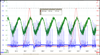
Today I had some time to play around, and I had a 1983 Honda accord in the shop that was headed for the scrap yard. I thought I would grab a few pressure waveforms from the engine before I pulled the trigger on it's long lived life. This car will not run, since it has an ignition problem, and a transmission problem. I have a pressure transducer screwed into the #1 spark plug hole. The green trace is a FLS transducer plugged into the brake booster hose. I could not trigger from a spark plug wire, since the engine will try to start, and there is no practical way to disable the fuel supply. I did hook an ignition probe on the coil wire, which was hooked to a spark tester, and I did get a very good idea of what was wrong with the ignition system. Capture #1 is with nothing wrong with the engine. I put this up so that you can use it as a baseline, and have something to compare the other captures with. [1983 Honda Accord, Engine/Propulsion waveform] Exhaust valve with the adjuster backed out all the way. The exhaust valve is only opening a very little bit. [1983 Honda Accord, Engine/Propulsion waveform] Intake valve that is only opening a very little bit. [1983 Honda Accord, Engine/Propulsion waveform] Auxuliary valve that is not closing all the way. With the engine cranking, the low compression cannot be heard in the cranking cadence. Notice the lower compression, and the difference in the lower portion of the waveform. You can also see the problem in the FLS capture (green trace) [1983 Honda Accord, Engine/Propulsion waveform] Exhaust valve with .025" clearance. [1983 Honda Accord, Engine/Propulsion waveform] Tight exhaust valve. The low compression cannot be heard in the cranking cadence. [1983 Honda Accord, Engine/Propulsion waveform] Tight intake valve. The low compression cannot be heard in the cranking cadence. [1983 Honda Accord, Engine/Propulsion waveform]
Feel free to comment,, and enjoy!
| |