|
I recently attended the ASA Connected CARS event in Detroit, Michigan, which brought together OEMs, suppliers, technicians, shop owners, technical trainers and others to discuss various topics, including: Automated Driver Assistance Systems (ADAS), security, V2V / V2S, OBD and much more. There's no doubt that the layers of technology currently deployed in fleets, along with future systems now being introduced, will present new challenges for the service industry. I found the sessions very enlightening and thought provoking, and recommend to any stakeholder to check out what ASA and other organizations are doing to bring about awareness of these new technologies, and the level of competencies that will needed to properly repair vehicles going forward.
We relish the opportunity to continue to provide a place for the advanced discussion that will be crucial in the years ahead. In that vein, this edition of the iATN Review is packed with some excellent examples of the challenges the industry is facing today, not only from a technical perspective, but from the shop management side as well. This includes parts acquisition, vehicle programming, basic electrical fundamentals, new belt technology, thermal imaging and more.
We hope you enjoy this issue of the Review.
Regards,

Scott Brown
iATN President

Rules are meant to be broken! Amazon for parts
Shop Management Forum
Donald from Texas
Yeah, yeah...I know....A customer wants to buy parts on Amazon and the typical repair shop owner will likely give a lecture on "cheap crap sold on the internet." Not so fast! We recently had an '05 Nissan 350Z here with a fried clutch. Ordered a complete clutch kit from WP in Exedy/Daikin. I was disturbed by the fact that the pressure plate was a completely different design from what we were replacing. The original had the self-adjusting feature. We tried this substitution on a different vehicle once before and the clutch dragged badly -- not going there again! So research on the internet gave us a part number for a LUK kit that appeared identical. Checking WP, O'Reilly etc. etc. it was NOT locally available but Autozone could get it in 3-4 days for almost $400. Amazon had the kit for $216 (+ tax and expedited shipping made it $260) and it got here in under 48 hours. Fit and worked perfectly and got the car off the lift relatively quickly. I put a decent markup on the kit and we ended up making more profit than with the questionable WP kit.
Then we had a Tundra with an ignition lock cylinder problem. Took it to our locksmith and it was repaired and two new (non chipped in this application!) keys were made. Our cost: about $70. Entire cylinder/switch assembly from the dealer : $170 as I recall and special order item. Well crap!! Turns out the electrical switch portion of the assembly is flaky causing intermittent no-crank. Dealer does not sell the electrical portion separate. No listing in WP, O'Reilly, etc. etc. Well guess what? A Google search takes me to two Beck-Arnley switch portions on Amazon and the excellent photograph confirms this is the identical part! "Buy now, only two left!" OK, I only need one. $26 plus tax and expedited shipping gets it here in under 48 hours. Truck made it back to the owner before the weekend and well before our promised ETA. He was back to making a living with it Monday.
We need to be flexible and resourceful in this day and age. Whining about "cheap crap internet parts" is not going to fly.
Intermittent LAN Failure Clues
Technical Discussion Forum
James from Florida
We see a lot of intermittent failures in the dealership. Most are either LAN or infotainment related. In either case, although the problem may not be current in the shop, there are usually clues to follow. How you follow these clues will usually mean success or failure in your repair attempt.
A 2016 Chevrolet Colorado WT came in today with an intermittent failure. It has 28,000 miles and the customer states that the ABS and SIR lights come on once a week or so for a few seconds and then go off. The truck ran normally and no lights were illuminated when I drove it around the block.
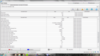
Doing a full module scan with GDS2, I saw codes set only in three modules, the EBCM, PSCM and SDM. This is clue #1 - all 3 modules are the only modules on the Chassis Expansion Bus. Let's see who is active on that bus.
OK, all 3 modules are present and currently communicating. Now, what codes are set?
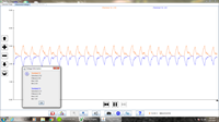
There's obviously a communication issue on the Expansion Bus. All 3 modules set U0077. This is clue #2 - When a modules is unable to communicate over the bus for 3 or more attempts, it will set U0077. At this point, it will suspend all message transmissions and will use default values for all parameters received over the bus. This will cease when communication is restored. So, all 3 modules lost communication at the same time. This points to a total LAN failure, not an individual module. How's the LAN voltages look?
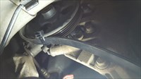
Well, we know that the problem is intermittent. The Chassis Expansion Bus looks normal right now. What can cause the problem? An open is unlikely as all three modules are equally affected. This leaves a short to power or ground. An intermittent short to power is very unlikely and I would expect a grounded LAN harness. Since we're dealing with only 3 modules in a LAN, it shouldn't be too hard to locate. With the LAN voltages on the screen, I started at the EBCM, then the PSCM and gently wiggled and pulled slightly on the harness with no change. The harness then goes up and under the UBEC before leading inside the truck to the SDM. When I shook the upper part of the harness, I saw this.
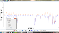
There's our ground out. Both CAN+ and CAN- are being pulled down. Following the harness past the UBEC, I saw it lying on an A/C line with the conduit worn in a concave fashion against the aluminum tubing. I pushed it against the tubing and saw this.
Well, that's pretty obvious, isn't it? Repairing the rubbed through wiring, installing new conduit and routing the harness away from the tubing solved the problem. With an intermittent, just follow the clues and proceed in an orderly, systematic fashion and you will be more successful with these type of failures.
Thermal Camera to Find Parasitic Drain
Technical Discussion Forum
Mark from Colorado
A 1999 Cobra Mustang came in with customer complaint of battery being repeatedly drained. Customer had to replace battery several times over last 5 years, vehicle has been to several shops. Customer often has to jump start vehicle because battery gets drained. I used low amp clamp to confirm 219 mA parasitic drain (knowing some of 219 mA was for module memory). Stabilized vehicle temperature in shop, then used FLIR E5 thermal camera to locate heat signature. Found heat in dash, disassembled dash, pulled radio and CD player, continued to use thermal camera to locate root cause for heat, found main amp under radio/CD (on top of transmission tunnel) on all the time, disconnected amp and drain went down to 17 mA at battery. Customer agreed to have me create "work around," so I set up a digital relay to only supply power to amplifier when key was on (rather than hot at all times).
An Easy Repair With A Little Thought
Technical Discussion Forum
James from Florida
A few days ago, a 2016 Chevrolet Express 2500 LS cargo van was towed in. It was a 2016 with about 500 miles on it. The complaint was "vehicle stalls on road, will restart." It seems strange to tow in for a stall only. It was almost closing time but I thought I'd drive the vehicle inside for the night. I went out to start it and when I turned the key, nothing happened. No click, nothing. The IPC illuminated and the headlights were bright. The Service Writer said there was no complaint of a no crank. Of course, with a commercial vehicle, you're not talking to the actual driver.
The next day, I went out in the lot to look at the truck and it cranked strongly and started right up. I drove it inside and scanned it and saw this.
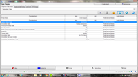
No codes set in any module...strange with a no crank situation. I let it idle in the shop for 2 hours with no stall and then shut it down to heat soak for an hour. After this, I turned the key and no crank. The security light was not illuminated. I didn't want to open the hood yet or disturb anything so I looked at scan data first. Let's see what the Theft Module is doing.
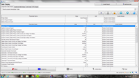
All these scans are with the key held in the crank position. The power mode shows a crank request being sent. Note the ignition voltage shows 0 volts. How about the BCM?
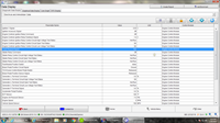
The ignition switch data shows a crank request also. Let's look at the ECM.
AHA. The ignition signal also shows 0 volts. The crank request shows yes, but the starter relay command is off. The most important clue is the engine control ignition relay feedback is 1.4 volts. Note several scan glitches...the oil pressure shows 7.5 psi and the VSS shows 158 mph. Scan data glitches are fairly common so be careful of what data is correct and which is false.
OK What can cause a stall and a no crank without setting codes? If the modules see no ignition voltage, they will assume that the key is off to shut down the engine and will set no codes. We show no ignition voltage in the TDM and ECM. G.M. has relabeled some relays. The engine control ignition relay is actually the run/crank relay.
During a start sequence, the ignition switch signals the BCM of crank or run mode and the BCM supplies voltage to the run/crank relay to actuate it. This supplies ignition voltage to several modules including the ECM. When the ECM receives this signal, it turns on the powertrain relay which powers up most components needed to run the engine. If the ECM does not receive this signal, it will not allow a crank and if it loses it while running, it thinks that the ignition switch was just turned off and shuts down the engine. neither case will set codes.
Our relay feedback is only 1.4 volts. I guess I could proceed with v-drop tests but the UBEC is buried on the Van chassis. It's easier to just swap the relay first. I swapped the A/C compressor relay with the ign relay and the vehicle cranked and started. I swapped them back and had a no crank again. At first, when I unplugged the relay with the key on, I listened for the relay to click then I realized that solid state relays are being used now and I wouldn't hear any noise.
In any case, the problem was only a defective relay and it was mostly diagnosed from the driver's seat with a little thought and a scanner.
Measuring Driveline Angles
Tool & Equipment Forum
Larry from Utah
Here's some information I posted years ago, but think it bears repeating. This is a 11:26 long video that takes all the mystery out of driveline angles, how to measure them electronically, and how much angle is "too much."
I also provide a link to the free app used in the video. Enjoy!
Voltage Dropping a Circuit
Technical Theory Forum
Wade from Colorado
A voltage drop occurs when current flows through a UNINTENDED resistance. It might be a bad ground, a wire with only 1-2 strands that are unbroken, burned relay or switch contacts, a corroded connector, etc.
Say you've got a car with dim headlights. You backprobe those headlight connectors with the engine running and the lights on, and you only measure 11.8 volts. Put those same DMM leads across the battery posts and you get 13.8 volts. You sir, have a 2.0 V Voltage Drop.
What happens if you unplug those headlights and stick your DMM leads in the socket? You'll measure 13.8 Volts. Huh? What? Why? Because no current is flowing! Your meter doesn't consume enough amperage to shock a flea. A circuit must be LOADED to measure a voltage drop.
Remember V=IR? If current (I) is darned near zero, so will the VOLTAGE DROP be.
So back to our headlights. Let's say these are 60 watt headlights. To make the numbers easy let's say the battery is 12V instead of 12.6 (engine off) or 13.8 (engine running). 60 watts = 12V times 5 Amps. So we've got (approximately) 5 amps flowing through that headlamp. If we've got a 2.0 volt VOLTAGE DROP, that means we have: V= IR 2.0V = 5.0A times .4 ohms.
SOMEWHERE in between the battery posts and that headlamp there is .4 ohms of UNINTENDED, UNEXPECTED, UNWANTED resistance that shouldn't be there. Oh, in HEALTHY wiring, switches, relays, connectors you might have a total of .1 ohms, but this is an unhealthy amount of resistance.
To make the headlights bright, you need to locate and eliminate that .3 - .4 ohms of unwanted resistance. You can NOT locate it by using your ohmmeter. The resistance is too low, your meter isn't accurate down there. You do it by measuring the voltage drop at each node along the way from the battery to the bulb. That includes the fuse, the headlight switch, the dimmer switch, the connector, everything on the plus side. And everything battery, cable, chassis ground, headlight ground on the negative side.
You put one lead of your meter on the battery post itself, and then "step" along the circuit until you see WHERE you are losing xs voltage. Once again, the headlight MUST BE ON! There must be current flowing in the circuit or that undesired resistance will have no, zero effect.
A whole lot of times you'll find a ring terminal, providing a ground for the headlights, screwed to the body, either corroded, on top of fresh paint from the body shop, whatever. It might have .1 or .2 ohms of resistance, IF you could actually measure it accurately. You can't. If you TRY, how hard you press your test leads against the terminal will change the reading... But you CAN measure the fact that on one side of it you have 0.00 volts, and on the other, 0.5 volts or more.
The question you SHOULD be asking is "How much voltage drop is acceptable?" In a headlight circuit, .2-.3 volts isn't going to make much difference. In an ECM, you want .02V or less. Otherwise all your sensors are going to read wrong.
So let's voltage drop that ECM!
First of all, START THE CAR! Unless the ECM is awake, powered up, and using current, you can't measure a voltage drop! DMM across the battery terminals reads 13.8V. DMM across the B+ and GND leads on the ECM reads 13.785 volts. Good enough! (Voltage drop of .015 V.) DMM across the IGN and GND leads reads 13.5 volts.....NOPE!
You've got a voltage drop in your IGNItion switch circuit you need to hunt down and kill. It's obviously NOT a bad ground because when you checked GND versus B+ all was good. It's on the positive leg.
Yeah, okay, you're either getting it, already got it, or someone else is going to have to 'splain it to you in some other fashion. If you still don't get it, PAY SOMEONE to teach you. Voltage dropping is the single most important skill you can have in this industry short of "righty-tighty, lefty-loosey!"
Stretch Belt Installation Tip
Technical Tips Forum
John from New Jersey
This may have been mentioned before, but is worth sharing. I had to replace belts on a Ford Edge today and none of my stretch belt install tools would work or fit in the confined area. I grabbed a heavy wire tie wrap and secured the belt to the pulley. Half a turn of the crank bolt with a ratchet and it popped right on. Obviously, this will not work of the pulley is "solid," but most are not. Hope this helps someday.
Programming G.M. Global A Modules
Technical Tips Forum
James from Florida
G.M. has become more stringent with security in Global A modules in 2016 - 2017 vehicles. More modules in each vehicle are involved in the security communications. Used modules are not going to be able to be installed any more without serious repercussions.
Today, I installed a new EBCM in a 2016 Colorado because of communications problems. When you attempt to program this module, the first screen that opens is a security screen prompting you to enter the vehicle security password. Since the ECM, BCM, IPC, HVAC, SDM, and EBCM store the environment security password, this password must be entered before programming. Also, the VIN present in the new module must be 00000000000000000. Also, all other security involved modules must have the same VIN entered in memory.
The environment security password is a one time entry as is the VIN and cannot be changed or overwritten. If the incorrect password is entered and programming is attempted, the vehicle will no longer run and the module will now be useless and must be replaced.
The password cannot be read with GDS2 from any module and can only be accessed in two ways. If you are a dealer tech or have a friendly dealer to work with, the code may usually be read through a key code lookup screen and is referenced as the immobilizer code. The only other way is to call G.M. Techline and give them the VIN. For this, you need an account and many hoops to jump through before the password is given out.
With some modules such as the ECM, the code can be saved from the old module and transferred into the new unit during programming. However, if your old module will not communicate, the new module can only be properly programmed with a VCI number from Techline. Even with the proper password, programming takes many steps and is time consuming. Of course, since the procedure takes 4 times more than it used to, G.M. has cut the times back once again.
Don't Let The Click Fool You
Technical Tips Forum
James from Florida
Today, a 2017 Chevrolet Malibu LT was towed in with a no crank failure. The customer told us that his mechanic said that the starter had failed as a click can be heard from the starter when the start button is pressed but the starter does not activate. It was towed to the dealer as it is still under warranty.
There were no codes set in any module. Looking at ECM data with key on engine off, I saw this.
Looks normal. Now, how about when the starter button is pressed?
OK,The ECM is receiving a start request and is activating the crank relay. I heard a click coming from the starter area. This is a stop/start vehicle and, as such, it uses two starter relays. One relay is used to engage the starter drive into the flywheel and the other is used to actually crank the starter. The starter solenoid has two control wires leading to it, one from each relay.
Why two relays? With the stop/start system, when the vehicle autostops, the pinion relay is activated, engaging the drive into the flywheel with the engine off. On the autostart, the other relay is activated, causing the starter to crank the vehicle. Why? because is shortens the crank time, making the autostart less noticeable. During a push button start, both relays are activated sequentially as a normal starter.
I pulled both relays and checked power inputs - OK. I jumped both relay connections and one caused the drive to extend and contract and made the click noise heard. Jumping the other relay connection caused the starter to free spin. This is normal operation. I hooked a test lamp to battery positive and probed the ground side of the starter relay and it illuminated with the start button pressed, showing that the ECM was activating the relay, but the relay was not functioning. A new relay solved the problem. No starter needed.
6.7 Cummins setting O2 sensor faults
Technical Tips Forum
Skyler from Nebraska
Just went through a battle on a Ram diesel setting multiple fault codes as follows:
P014D 1/1 O2 sensor slow response lean-rich P013b 1/2 O2 sensor slow response lean-rich P0471 Exhaust pressure sensor performance P1451 DPF system performance P2463 DPF soot accumulation P242F DPF filter restriction ash accumulation P2bac NOX exceedance deactivation of egr
To start out with these are usually fairly cut and dry. We may or may not have a soot issue. If a over fueling condition is found it needs to be identified and corrected. Next I will typically begin by performing tsb 25-003-13 (if it has not yet been performed) which involved replacing O2 (1/1 and 1/2 sensors) harness with a overlay. Also making sure the O2 sensor module feed and bus circuits are gold plated terminals (overlay comes with gold pins for all terminals). If they are found to be tin then install gold terminals. Next is to remove O2 sensors and blow soot out with compressed air. Cleared faults, Regen if needed and test drive. Perform zero fueling events on road test by going wide open throttle and then immediate deceleration coast down. If MIL comes back on replace O2 sensors. If the DPF soot load is too high generally driving them on the highway for 50 miles will allow the PCM to perform a active Regen and will return to a normal soot load. If not DPF gets replaced. So like I said before not too big of a deal.
In the case of this particular truck the engine ran great and everything tested out in relation to the O2 sensors and after treatment system. What enviably repaired this vehicle was replacing the Mass air flow sensor. The only way I was able to spot this was from doing a data recording on this and another know good truck and comparing. Found that at a stable idle the MAF was under reporting by 3-5 G/S. Also the Baro was slightly elevated (28.6 on customer truck and 28.1 on donor truck). I will say that using the Modis in OBD global mode as apposed to Witech was the best way to view this.
Surprisingly the MAF was the root cause of every fault code listed above. In the case of a Cummins wide band O2 sensor, and information found flow charts, chrysler dca books, and service information indicate that the MAF does not have any bearing upon the PCM's ability properly verify O2 sensor operation. Obviously this is incorrect. O2 sensors on Cummins 6.7 are not used for fuel mixture purposes as a diesel does not trim fuel like a gas engine. According to SI the primary purpose is to control/verify EGR. I do think that they also have a hand in the regeneration process as well. Evidently the pcm is using intake airflow to judge if the O2 sensor current is near enough to what is expecting to see. In this case I think the PCM just was not capable of blaming the MAF so it blamed the O2 sensors. There was no information to suspect the MAF in Star online, identifix or IATN so hopefully someone can benefit from this in the future.
| |