|
Welcome to the iATN Review, where we share with you some of the top-rated discussions posted on iATN in the last quarter. In this issue, we have great contributions by Martin from British Columbia covering GM LAN / High-speed CAN Bus, and a case study covering the use of the NVH analyzer by PicoScope that GM uses in their dealerships. James from Florida shares with us a 2017 Chevrolet Volt with a battery balancing failure, and air bag loop resistance problems found on late model GM vehicles, and how he's been able to properly analyze and solve these issues. Additionally, we have a nice demonstration on the use of thermography when analyzing a potential battery problem, fuel pump waveform analysis, and a management discussion about online reviews.
We hope you enjoy this edition of the Review!

Scott Brown
iATN President

Effects of Conditions on HS GM LAN (HS CAN) Bus
Technical Tips Forum
Martin from British Columbia
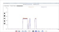
Some have asked what effects might be noted when using the GM Data Bus Diagnostic Tool when various conditions occur. The images in this post were captured from a pair of mock-up boards used in training.
Note: I captured these shots using the DBDT and MDI a while ago, before updates to the DBDT software and before my MDI 2 arrived. Since the software updates have increased the speed approximately 25X, cleaner signals may be noted in future images.
A 2010 Camaro and a 2008 GMC Sierra are represented in the graphs. Please bear in mind that these are mock-up boards, not actual complete vehicles and not all modules may be present.
Adding or removing modules has an effect on the overall shape of a graph, but what will be demonstrated here is the general effect of grounding various Bus terminals, opening or shorting to voltage.
This image represents an at rest [HS GM LAN] plot using the DBDT of a normally operating system on the 2010 Camaro HS GM LAN.
Here is [Diagnostic Data Bus Tool Graphs] the graph when Bus + is grounded
Bus - grounded [Bus - Grounded].
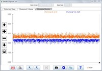
This plot represents normal voltages when the 2008 Sierra HS GM LAN (HS CAN) is active [Data Bus Normal]
Here is the "Detected State" for normal activity. [Diagnostic Data Bus Tool "Detected State"]
This plot identifies the condition when a BCM connector was disconnected at the BCM [Open Connector Graph] (Note the plot scrolls from right to left of the display)
Here is the effect of removing the 120Ω Termination Resistor during normal Bus activity. [Termination Resistor Removed]
This image identifies the effect of Bus - grounded [Bus - to Ground]
Normal Bus activity [Normal Activity]
[Open HS GM LAN] shows the effect of a connector backed out of the Electronic Brake Control module.
Here is the Measured Voltage scree with the Bus shorted to B+ [HS GM LAN Bus Shorted to Voltage] and the Detected State [Detected State Short to B ]
[Bus Shorted to Ground] demonstrates the effect of the Bus shorted to ground.
Vibration Diagnosis Technology
Technical Tips Forum
Martin from British Columbia
Some active dialog is taking place in a current Industry Issues thread, as posted by iATN's resident poster of "All Things doom and Gloom" Ozdjan Hassan, who manages to dig up and air the "dirty laundry" in the automotive industry. Hmm, do they build cars in Cyprus? VBG.
The fact of the matter, on the trucks in question is that not all trucks of the exact same build exhibit the same or any concerns and the main contributing factors that are most common, appear to be an extremely stiff chassis and body assembly reacting to tires of questionable quality. Understanding the dynamics of resonant frequencies, source (transponder), transfer path and responder (seat/controls) allows technicians some opportunity to effect improvements.
However, some natural resonant frequencies are inherent to various vehicle components and it can require significant re-engineering to eliminate or engineer a resonant frequency out of the objectionable range.
GM and tire engineers in their attempts to diagnose some problem trucks have gone through several tires before identifying a set that is truly acceptable quality. Many times that is still the issue, but a slight degradation of tire could cause the same concern at any time. Vehicles do perhaps need to accommodate and tolerate the less than perfect environment and adapt for wear on components a little better in some cases.
So, knowing that no vehicle will have perfect tires for all of it's lifetime, even beyond the first tire rotation in some cases, improved isolation, mass dampening and mount stiffness may be just a few ways to address transfer path issues, if the source (mostly tires and wheels) cannot be made "110%" perfect.
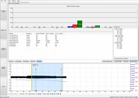
For those discussing such issues of vibration without knowledge of current vibration diagnosis technology available, they might just as well pack up and go home, since it can be extremely challenging even with the most current technology available to technicians. All GM dealerships must now use the PicoScope with NVH kit for vibration diagnosis.
Many technicians have attended training to date and benefit from this tooling, over it's predecessor, the EVA, before that, VAL, sirometers, reed tachometers etc. I've used them all and the difference between the old and new technologies is the level of G force that can be measured and identified to be typical of components or assemblies. The EVA was okayish, but cannot measure down to the milli Gs or micro G forces that are creating concerns with current technology vehicles.
Since the introduction of the PicoScope with NVH kit which I've had for well over a year now, the scope itself has been updated to the latest and greatest and the introduction of the 3 axis sensor is the biggest improvement over the single axis sensor. The sensor when mounted properly will accurately display the XYZ axis (direction) of the dominant frequency in bar graph. At the push of a button, to the default setting, the consolidated value is displayed, similar to the single axis sensor of a year ago.
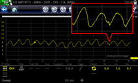
Here are some screen shots of an induced vibration from a couple of weeks ago, but more importantly, I encourage those of you who not familiar with the tool to look at what is being displayed. In other words take a look at E1 and E2, P1, P2, T1, T2, T3 etc, to get an idea of what is being displayed.
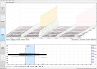
Take a look at various methods of displaying the data, frequency, 3D frequency, bar graph, RPM order, road speed, etc. Think of this as having the same characteristics as John Kelly's Vibrate Software, because it does.
This screen shows the option to "Add a Vibration" that is not in the default display, such as an Active Fuel Management order[2006 Pontiac Solstice, Engine/Propulsion Scan Data].
In the 3D frequency mode, I have manipulated (stretched out) the graph for improved viewing)[2006 Pontiac Solstice, Engine/Propulsion Scan Data]
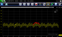
This view shows the 3 axis sensor being used in consolidated (default) mode, looking the same as a single axis sensor bar graph.[2006 Pontiac Solstice, Engine/Propulsion Scan Data]
Here we are viewing in RPM order mode. Look at the 3 axis "XYZ" sensor plots (red, blue and green) and sympathetic frequencies [2006 Pontiac Solstice, Engine/Propulsion Scan Data]
Of course, my old reed tachometer and the EVA will do that too, but those tools are not suitable as a primary diagnostic tool on current technology vehicles.
A comment was made in regards to Active Fuel Management effects, which can be monitored by selecting the "Add a Vibration" option which opens a menu and selecting the appropriate value that would correlate to an engine in AFM mode.
This really is the best viewing technology readily and economically available to technicians, especially when compared to some very expensive engineering level alternatives.
By the way, in the set up menu, instead of choosing the MDI 2 as I did, if working on a non-GM vehicle, a generic low cost "ELM 327" interface can be selected.
Regards,
G.M. Vehicles With Loop Resistance Problems
Technical Tips Forum
James from Florida
Most late model G.M. vehicles have inflatable restraint loop resistances that can be accessed through a scanner. This greatly facilitates diagnosis/repairs. Today, I worked on a 2016 Chevrolet Equinox with 6 miles that had a SIR lamp and service warning on during PDI.
Step 1 ... What code is set?
[CODE SET]
OK - B001A-0E - driver's side seat belt anchor pre-tensioner loop resistance low.
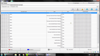
Step 2 - Check resistance of pre-tensioner loops. I selected loops 1 -14 to check with GDS2.
[Resistance Readings]
All loops have about 2.5 ohms resistance except for loop 7 which is low at .4 ohm. The problem could be anywhere from the SDM to the anchor pre-tensioner or associated wiring harnesses.
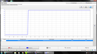
Step 3 - Check for a grounded harness under the seat. I graphed the resistance while gently moving and wiggling the harness under the seat.
[Resistance Loop 7]
No change noted there. We can start testing from either end of the circuit, but, since I'm already under the seat, let's just unplug the anchor pre-tensioner first.
Step 4 - unplug pre-tensioner
[Unplugging Pre-tensioner]
Well, that's pretty obvious isn't it? The tensioner is internally shorted. Time to replace the anchor and retest.
Step 5 - Confirm Repair
[New Pre-tensioner]
Loop 7 is now in the normal range and the service light is off. Just need to clear the code and ship it. A lot easier than plugging in resistors or simulators, isn't it?
Thermal Camera to Verify Battery Failure
Technical Discussion Forum
Mark from Colorado
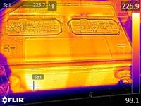
2009 Suburban came in today with a complaint that the instrument cluster displayed a message "Service charging system and/or battery". Customer indicated the voltmeter needle displayed about 13.5 VDC (and usually was much higher). This vehicle has a "main" battery and an "auxiliary" battery. When I opened the hood there was a strong odor of sulfur or sulfuric acid. I used my FLIR thermal camera and captured images of the main and auxiliary batteries. I have attached a thermal image of the auxiliary battery. [Failed Battery, Charging light on] In the image you can probably see three of the six cells are very hot. The second cell in the battery appears to have a hot spot about 225F, the entire battery was near 200F. Additional images that I captured indicate how hot the alternator was at this time and the the positive cable (in parallel configuration) was warm especially at connections.
After testing both batteries and confirming battery "date" codes several years old, we replaced both batteries. The charging voltage returned to over 14 VDC and the alternator was not "working so hard". The instrument cluster no longer had the warning message.
2017 Volt Cell Balancing Failure
Technical Discussion Forum
James from Florida
Probably, most people on this list have not dealt with a Volt unless they are dealer techs. IMO, the Volt, even though it uses over one million lines of code (more than the Space Shuttle), has proven to be one of the most reliable vehicles that G.M. produces.
Naturally, problems will occur with any vehicle. Today, I repaired a 2017 Volt with 2600 miles. The 2017 is the new generation Volt with the more powerful battery, different engine and transmission, and many refinements. The complaint was SES light is on. Scanning the vehicle, I found P1E9E set in the HPCM2. This code is set due to a battery cell group inbalance. In this case, the Interface Control Module 3, Cell Balancing Circuit.
To maintain a similar state of charge on the cell groups, the HPCM2 looks at the cell group voltages and determines which cell groups need energy removed in order to maintain the battery groups at a similar state of charge. This is called cell balancing.
There are no diagnostics for this code as it can only be set due to an internal problem in the BECM, preventing cell balancing to occur. The BECM is mounted above cell group 2 in the HV battery and requires battery removal to replace.
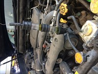
If you've never seen a Gen2 Volt, here's the engine compartment.
[2017 Chevrolet Volt LT, Photo]
The HV battery lowers out the bottom.
[2017 Chevrolet Volt LT, Photo]
These are the battery connectors and coolant ports.
[2017 Chevrolet Volt LT, Photo]
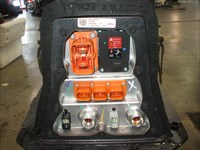
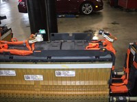
This is the battery with the cover removed. This entire pack is live and great care with the use of PPV equipment is mandated at this point as the pack voltage is 360 volts and will kill you.
[2017 Chevrolet Volt LT, Photo]
This is the BECM mounted above cell group 2.
[2017 Chevrolet Volt LT, Photo]
This last picture shows the pack with the BECM removed. It has 8 connectors and each connector must be unplugged in the correct sequence or damage may occur. Reattachment has a sequence as well. The new BECM needed programming after vehicle reassembly and solved the problem.
[2017 Chevrolet Volt LT, Photo]
Fuel Pump Waveform Study
Technical Theory Forum
Andy from Arizona
I recently scoped a fuel pump and noticed a couple of things about the waveform I was not sure about, so I am hoping to stimulate some thought and conversation here.
This fuel pump uses eight commutator segments, so every eight oscillations in the waveform should translate to one revolution of the armature. It is my understanding that, when viewing fuel pump waveforms at higher time scales and observing [an additional arch pattern for each revolution of the armature], this is an indication of worn armature shaft bushings, allowing the armature to wobble as it rotates.
Looking closer at this fuel pump waveform, I noticed one commutator segment consistently displayed [a unique blip in the pattern]. I am curios as to what might be the cause? What have you seen?
Also, again viewing the waveform over a longer time scale, I also noticed (what appeared to me to be) an interesting irregularity in each complete revolution of the armature. For the first half of the revolution, one can see each commutator segment using slightly more current than the last, which I assume is due to a decreasing gap brought on by the armature wobble. But then, for the second half of the revolution, the current suddenly drops for the next commutator segment, and then slowly rises again for three of the remaining four segments, similar to the original four, before dropping again for the final segment, [as highlighted here]. I am left pondering what is occurring to create this consistent pattern as well.
Please offer your thoughts on what may be contributing to these fuel pump patterns (maybe some of our illustrious iATN fuel pump guru's will chime in and offer their explanation as well).
Easier Block Test
Technical Tips Forum
Leo from New York
I've only done this with Subaru's so far, but it definitely makes it easier to find the sneaky ones. Take off the vacuum bulb, suspend the tester and plumb it right into the reservoir nipple. Any combustion gases in the radiator get forced right through the test fluid, without coolant contamination or the hassle of holding the tester at the radiator neck while also revving the engine.
[Easy]
Online Review Response
Shop Management Forum
Mark from Michigan
I received an email from a client asking for my thoughts regarding a negative online review. Following is a brief account of the situation, followed by a draft of what I thought would be a good reply to the review, as well as my rationale for posting a reply. Curious as to your thoughts.
BACKGROUND: The first experience with this customer involved a request to have his own parts installed. This is not something this shop normally does, but for various reasons as an act of kindness the shop owner decided to help the guy out. In so doing he made it clear that he's going against SOP and that this was a ONE TIME deal. The customer reportedly left happy. A week later he came back wanting more work done with his own parts. The owner declined. The customer asked how much the shop would sell the parts for. He apparently didn't like the price and left. A short time later this review was posted online:
- - - - - - - - - - - - - - - - - - - - - - - - -
Nice people, but unfair pricing. I get that any small auto repair facility needs to "mark up" the parts they order but these fools mark them up at more than double what they paid. That's not a matk up it's highway robbery when you can get the same exact part at gmpartsdirect for less than half of what these scam artists pay
-- - - - - - - - - - - - - - - - - -- - - - - - -
My client asked my opinion regarding the following: Should I contact the customer to see if he can be reasoned with and convinced to pull the review? Should I post a reply to the review? Should I just ignore it and chalk it up to knowing that we can't please everyone every time?
HERE ARE MY THOUGHTS, which I shared with my client: First, I didn't think contacting the customer and trying to reason with him was prudent. By the customer not listening or choosing to ignore what he was told originally about the installation of his own parts being a one-time deal, he has demonstrated that he only hears what he wants to hear. I put this question to my client: How far are you willing to go in pleading with him to remove the review?
Next, I stated that I thought there would be little to be concerned about if he chose to ignore the review. I stated that (to me) the guy sounds like one of those 'the world is out to get me' types. I further stated that any time I see name calling in a review ("fools" and "scam artists") it loses credibility with me because name calling is emotional and petty and is simply a way to make one's own self look good by making the other person look bad.
However, I suggested that this review is actually an opportunity to explain how it's in the best interest of all motorists to allow the service facility provide the parts. Here's the draft of what I suggested as a reply:
Everyone wants a good deal. No one wants to pay more than they should. We certainly get that, after all we are consumers too. But let's put things in proper perspective. First, there are indeed sources where you can buy parts at discount prices, and for those doing their own work, that may be an okay option. HOWEVER, as a professional automotive service and repair business, that option is not right for us. Why? For starters, our customers tend to demand (and rightfully so) that we provide a warranty - labor AND parts. Therefore, it's important that we buy parts of high quality from a vendor we can trust. Second, it's important to buy parts from a vendor with whom we have a relationship, that shares our values with respect to quality and customer satisfaction, and will promptly provide us with replacements parts, without jumping through hoops, should the need arise. Does this mean sometimes paying a little more? Yes, but we believe that in terms of the OVERALL VALUE it is well worth it. Fortunately most of our customers understand and appreciate this.
I haven't heard yet what the shop has elected to do. Perhaps others here have some thoughts.
| |