|
Welcome to the June edition of the iATN Review. In this issue, we have a number of interesting articles, including more great submissions from long-time GM dealership technician, James from Florida. One features an Intelligent Network Diagnosis case study covering the use of the GM MDI and Data Bus Diagnostic Tool which provides some great perspective on GM vehicle networks, and another where he was able to solve for an intermittent on a 2015 Camaro for a customer who was on the edge of forcing a vehicle buy-back. Chris from New Jersey has a two-part discussion about building your own coil tester. We've also highlighted discussions on handy household cleaners, some cool tips on GM ECMs for the HFV6 3.6L’s, how to look up blank TCM part numbers on Nissan vehicles, a look at an internally failed ECM ground circuit, and much more.
We hope you enjoy!

Scott Brown
iATN President

Intelligent Network Diagnosis
Technical Discussion Forum
James from Florida
Network diagnosis is actually fairly easy if you proceed in a structured manner. There are usually many clues to follow. Just don't jump ahead of your diagnostic path.
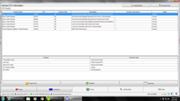
Today, a 2014 Silverado was dropped off with a complaint of ABS and brake light on, Sir light on, Service Tire Pressure System and Service Brake System messages displayed and IPC gauges inop. Clue 1: Seeing problems with several different systems at the same time usually means a communication failure. Step 1, Which modules are presently communicating/
[2014 Chevrolet Silverado 1500 LT, Scan Data]
Clue 2: All the non-communicating modules are using terminal 1 which is the low speed LAN. Step 2, What codes are set?
[2014 Chevrolet Silverado 1500 LT, Scan Data]
Several codes set by high speed modules. No low speed modules have coded. The problem appears to be restricted to the low speed LAN. Let's take a fast glance at the high speed LAN.
[2014 Chevrolet Silverado 1500 LT, Scan Data]
[2014 Chevrolet Silverado 1500 LT, Scan Data]
No problems seen here. Let's see what our low speed LAN is doing on terminal 1....
[2014 Chevrolet Silverado 1500 LT, Scan Data]
No low speed modules detected on the LAN. A fast look at LAN voltage will show us why.
[2014 Chevrolet Silverado 1500 LT, Scan Data]
No communication at all. The low speed LAN is a zero to 5 volt system but it's fixed at 2.78 volts. Why? Can it be a short to power? No, the voltage would be higher than 5 volts. How about a short to ground? No, our voltage would be close to zero. Most likely there is a module pulling down the LAN voltage. What's the easiest way to find out which one? Simple resistance testing.
Key off, 2 minute time out, the resistance between terminal 1 and ground is 365 ohms. I would expect to see high kilohm to low megohm readings. Checking the first splice connector, JX200 and pulling the comb, there are 7 component connections. Checking the resistance on each connector, all are very high resistance readings except for terminal G, ckt 5060. This reads 121 ohms. Circuit 5060 leads to the radio.
I pulled the radio and found an aftermarket module wired in behind the radio. I have no idea what it's used for. I unplugged this module and re-installed the splice connector comb. With key on, let's look at the low speed LAN voltage now.
[2014 Chevrolet Silverado 1500 LT, Scan Data]
Looks good now. What modules are communicating?
[2014 Chevrolet Silverado 1500 LT, Scan Data]
OK. All systems are now go, except for the radio which is unplugged. We told the customer that the problem is with the aftermarket module and is his concern now to repair. This entire diagnosis, by proceeding in an orderly fashion, took no more that 20 minutes. Always proceed from A to Z in network diagnosis and you won't get stung.
2015 Camaro Intermittent Failure
Technical Discussion Forum
James from Florida
I have had a 2015 Camaro in the shop for about a week now with an intermittent problem. The customer purchased the car from another dealer who can't repair it and told the customer that the failure would have to become more obvious to be diagnosed. She called Chevrolet to complain and the zone told her to bring it to us.
The car has 4000 miles with a problem that is very intermittent. To duplicate it, the customer states that the vehicle has to be left overnight in cold weather and, directly after starting, needs to be driven very rapidly across railroad tracks. When these conditions are met, the red brake light on the dash will flash on and off 1 time and will not re-occur again until sitting overnight again in cold weather. We're in Florida and cold weather is not easy to come by.
We gave her a loaner and told her that we needed the car for two weeks. The first 4 days were warm but I tried driving the car anyway. We have a railroad crossing about 1/2 mile from the shop. The problem didn't occur and no codes were set in any module. (They may have been cleared by the selling dealer)
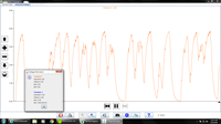
The next day turned cold and I drove the car over the tracks almost fast enough to launch it. The red brake light did flash 1 time....Wow. Rescanning the modules, the BCM set a history code for lost communication with the EBCM...A CLUE. Well, that takes a lot of possibilities out of the picture. It sounds like a data transmission problem. I hooked up a laptop to the DLC to monitor the LAN with the GM testing tool and let the car sit for 4 hours then tried the tracks again. This is the main high speed LAN on terminals 6 and 14.
[2015 Chevrolet Camaro LT, ECM/Inputs/Outputs Waveform]
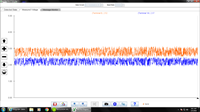
The light flashed again and this waveform shows no obvious problem. The EBCM resides on two LANs, the main LAN and the chassis expansion LAN. A com problem on either LAN can cause communication losses with the BCM. I let it sit overnight and tried it again with the LAN tool watching the chassis expansion bus on terminals 12 and 13. The light actually flashed twice this time and I see why.
[2015 Chevrolet Camaro LT, ECM/Inputs/Outputs Waveform]
I would expect to find a loose wire or terminal. Temperature can cause expansion or contraction as well making the condition worse. The chassis expansion bus leads from the EBCM through the firewall to the steering angle sensor and the multi-axis acceleration sensor. How do we decide what to test? The LAN is a two wire twisted pair. Looking at the failure, both LAN+ and LAN- dropped out and resumed exactly at the same time. What's the odds of that? Not very good.
The EBCM could be losing power or ground, but in that case, I would expect the multi-axis sensor to have stored a communications code as well. What's next? Well, all high speed modules need a independent communications enable 12 volt circuit for wake up. The EBCM com enable circuit is shared with other modules through a splice connector, J202 but is fed independently through one branch that goes through connector X104, terminal 1 under the hood. I back-probed terminal 1 with a voltmeter in min/max mode and drove around the lot hitting speed bumps as hard as I could and I saw drops from battery voltage on my meter over the bumps. Good - CLUE 2.
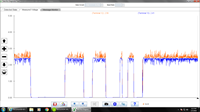
The J202 splice connector is in the dash wiring harness just below the inside fuse block. I was able to reach up under the dash and squeeze and wiggle the harness in this area while watching the waveforms on terminals 12 and 13 and saw drop-outs occur. I cut open the harness to expose the splice connector, circuit 5986 and cut off the splice tape. I found bare wires lying side by side without a crimp splice installed, just splice tape. Nice factory wiring job. I soldered the splice and retaped the harness. The next two days, I drove the car under similar conditions and saw this....
[2015 Chevrolet Camaro LT, ECM/Inputs/Outputs Waveform]
The vehicle is repaired and gone and the customer is overjoyed. The threat of a buy back is eliminated and we grew a new customer.
Looking Up Nissan Blank TCM Part Numbers
Technical Tips Forum
Scott from Michigan
Due to a recent discussion on the topic, I decided to do some investigating and found an easy way to lookup TCM part numbers:
parts.nissanusa.com
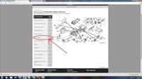
Click on the parts tab at the top and you will need to enter your vin and click set you will then see this screen [nissan tcm]
Selecting powertrain will bring you to this screen [nissan tcm]
Selecting auto transmission transaxle and fitting will take you to this screen [nissan tcm]
Select automatic transmission (not blank or reman) will take you to the part number [nissan tcm]
DIY Coil Tester - Part 1
Tool & Equipment Forum
Chris from New Jersey
Many years ago I found myself diagnosing Ford COP ignition coil units, but I didn't have great equipment (or training) to do this well. One test I did have was to manually stress test the coil- using an adjustable spark tester to check maximum output. This was impractical to do on the car/truck. I didn't find any production tool to bench test coils, so under the unwholesome influence of TV shows like MacGuyver, A-team, Junkyard Wars,&Mythbusters I went & made my own. ;)
Basically it was a window motor that spun the top half of a Ford TFI-IV distributor- all mounted in a large molded case. It worked well enough, but as I gained knowledge & experience, I used my scan tool or scope more, & the spark tester (aka "Sparky") less.
Nowadays I still find occasional use for bench testing a coil. Maybe I want to stress a suspect unit that didn't show anything on a scope (no symptoms in the bay but codes or mode6 points towards it), or check coils that are going back under an intake plenum after a plug change, or just to check functionality of a new part.
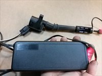
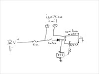
I wanted to "update" Sparky to something a bit more compact, so here's what I came up with- Sparky 2.0. [DIY coil tester in use] Connect the coil to the tester & see if it can fire a 3/4-7/8" spark gap. Works on 2-wire COP units like Fords or Chryslers, or most any "hei" type coil. The basic idea is that a square wave signal generator drives an ignition module- that fires the coil. Here's the functional block diagram. [DIY coil tester block diagram] The diode provides reverse polarity protection.
The signal generator is based on the NE555 timer chip, you need one that has two potentiometers to adjust frequency AND duty cycle (Left one changes freq, right one changes duty cycle & freq- the jumpers change freq ranges). [NE555 signal generator] Input spec is 5-15Volts- output voltage is very close to input level- about 200mA max. Find it on ebay, amazon, etc. for $2-4 each. Buy several as it's easy to fry the chip if you're not careful- reverse polarity, short the output, etc= poof. The unit uses a 3-pin "DuPont" 2.54mm pitch connector- it's similar to stuff used in desktop pc's - mine came from an old pc case cooling fan. I adjusted the 555 timer so that it outputs a 12V signal with a 3ms neg/0V pulse(max positive duty cycle) at 8Hz or so.
The ignition module is a Ford TFI-IV "black" remote mount unit (Standard Motor #LX-241T). Special thanks to Albin Moore for his recent (& timely) post on Ford ignition systems. This computer controlled dwell module charges the coil as the SPOUT signal goes from 12V-0, then fires as it goes 0-12V. The module current limits ignition primary at 6.5-7.0 Amps. I didn't have a TFI connector on hand so I used some female terminals that fit the module pins securely then filled the module cavity with hot glue & gave it a wrap of duct tape. Here's everything stuffed into a plastic case I had laying around- I added a couple LED's for power & triggering status. [Inside the coil tester]
DIY stuff isn't for everyone, but I enjoy "tinkering" in my spare time, & if it produces something useful, then it's a real win-win situation in my book.
DIY Coil Tester - Part 2
Tool & Equipment Forum
Chris from New Jersey
I'm back again with my second installment for another type of homemade COP coil bench tester. This design is to control a 3 or 4 wire coil with an internal module- ie. the primary switching transistor is part of the COP unit. Now what I came up with is a small device that makes a 0-5V squarewave with 3msec on-time at 15Hz.[DIY mini coil driver] So you could just buy an adjustable signal generator that would do the same thing, but where's the fun in that? ;)
Most 3 - 4 wire COP coils function about the same; power, ground, and a control ckt (4th wire might be another ground or coil feedback ckt). The control signal is usually a squarewave (around 0-4V to 0-5V), when it rises the coil starts charging, when it falls the coil fires.
This build is based on another NE555 signal generator. This unit has an on-board output transistor that is rated at 500mA - higher than most other units that just use the driver inside the 555 chip(100-200mA). [NE555 squarewave] Sourced from ebay (a dozen sellers have this- I'm sure from the same factory)
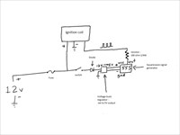
So here is the block diagram. [block diagram for DIY coil driver] Battery power goes through a fuse (7.5A)&splits to the COP (+) & a momentary switch. From the switch power goes through a diode for reverse-polarity protection, then to a DC-DC buck regulator - converter [Mini DC-DC buck converter] - also ebay. The adjustable converter is set to reduce voltage from 12V to 5V. 5V into the NE555 generator produces my 5V squarewave. There is a 1/4W resistor (about 100 ohms) in the output ckt to protect the 555 unit from shorting the signal to ground (overload).
There you have it. I find it's a nice tool to have- not often but sometimes. For about $15 plus some scrounged bits. Connect the power, ground(s) & signal leads, add a spark gap tester, then hit the button.
A List of Household Chemicals That Come in Handy
Technical Tips Forum
Stephen from Virginia
Over the years I have been on iATN, I have read and heard of several tips for chemicals and over the counter non automotive tricks that work in a pinch. This is a thread that needs to be easily searched when someone has an issue.
Read on to see what household chemical tips iATN members shared...
LY7 and LP1 ECMs, GM 3.6 HFV6
Technical Tips Forum
Russell from Florida
I don't know how long this tip will be applicable but starting late last year, I noticed it most starting in November, there have been a much higher rate of failed new ECMs for the early HFV6 cars, LY7 and LP1 engine RPOs. The service part number is 19260507 for the ECM in OE.
The typical failure of these ECMs leaves the key stuck in the ignition, the fuel and coolant temp gauges stuck all the way to the left and the security and traction control warning lights on. When you install a new ECM before programming it if it is a good ECM the key should begin releasing, the fuel and coolant temp gauges should begin working, and the traction warning light should extinguish.
If you are certain of your diagnosis, which is easily accomplished by looking for all the class 2 modules except ECM to be present on the class 2 message monitor and by looking for an active class 2 line at the ECM with a scope as well as power, grounds, and main relay activity, and your new ECM will not program and does not extinguish the traction light, restore the fuel and coolant temp gauges, or allow the key to be removed your new ECM is defective.
I have seen reports and fielded calls and emails where the shop asking for help has had to install as many as 5 new ECMs in order to have one that successfully programs. This tip is about that as well as how to identify an ECM that has no chance of successful programming before wasting your time or second guessing your diagnosis or equipment. I use an MDI and my laptop is up to the specs and beyond. And I have experienced at least one bad "new" ECM.
Good reman ECMs will allow key removal, restore fuel and coolant temp gauges, and will not light the traction warning light. If your replacement ECM fails to do all these things. Don't bother attempting to program. Just get another one (or two or three) and try until you get a good one.
2004 Trailblazer 4.2L Blown PCM Sensor Ground
Technical Tips Forum
John from Pennsylvania
Another shop called me a while back. They had a PCM that was generating high voltage codes for both of the APP's, one of the TPS's, the iAT (plus a few more). I had them test and the PCM wasn't supplying a ground for all of these inputs. By temporarily bypassing the PCM's ground the vehicle functioned normally. Once they proved that the PCM was bad they had me program the replacement and set up the security. I stressed concern that something didn't feel right and this may well have been caused and didn't just happen. They assured me that they looked and didn't find anything.
A week later they called back, same problem.
Upon arriving I retested and confirmed that the ground circuit had failed inside the PCM. Opening it up, it was easy to see the trace that was burnt off of the board. It was also easy to repair with a jumper soldered into place.
That left the question as to "why"? Worse yet how can we find it without tearing the whole car apart. It turns out this ground path affected five ground circuits. Somehow power was being applied to one of them. To find it efficiently was going to take some creativity.
All five grounds involved were labeled and removed from the PCM connector. They were then jumped to ground through a fused jumper. Now this would work with one current probe but it would be more tedious and would require first testing a group of three and then the other two in hopes of capturing a current spike. Having three current probes allowed for the following routine.
The grounds were numbered 1-5.
Grounds 1,2,3 were captured with one current probe connected to channel A.
Grounds 3,4,5 were captured with one current probe connected to channel B.
Grounds 2,3,4 were captured with one current probe connected to channel C.
Making a logic table a spike on only channel "A" was ground #1, on channel "B" was #5.
A spike on two channels "A&C" was ground #2, and "B & C" was #4.
A spike on all three channels was ground #3.
The spike occurred on B and C indicating ground circuit #4 which was the AC pressure transducer. The idea of course at this point was to identify the affected circuit so that only it had to be closely examined. It was notable that the spike only occurred when hitting bumps, under load with the headlights turned on. What was found was a parking light feed wire that was sticking out of its harness and was touching the pressure transducer harness where it exited the engine harness. These two wires, the parking light and the AC Pressure sensor ground both had a tiny spot abraded where one strand of the wire was visible and when they touched was putting 12v into the sensor ground circuit for the PCM.
I hope you never need this routine, but if you do I hope it helps.
People Person (Hard Lessons)
Shop Management Forum
Louis from Louisiana
Speaking with auto shop owners, I often hear, "I'm not a people person." I believe the things we do effect how others react to us. For instance, those who think others are out to get them will find a lot more negative interactions. Alternatively, those who feel others are just people like themselves tend to have less negative interactions.
At a young age people begin to form their views of the world. If the environment appears hostile, they tend to view people one way. Others see people as friends or at least pleasant to be around. I feel career choice also factors in. People who depend directly on the approval of others, like salespeople, tend to develop better people skills. Others working in technical fields, lack the direct interactions and may concentrate more on other skills.
This was a problem for me and with great effort I have gotten much better. I share a few of the things here that have helped me and hope other may add to the list.
1.) Discipline reduces chaos and lack of chaos makes it much easier to deal with the normal problems of life.
2.) An organized environment prevents many small annoyances that put people on edge and cause them over react.
3.) Time off and enjoyable recreation is as important to success as working hard. Without down-time, small things tend to become big things.
4.) Because something is thought does NOT mean it needs to be verbalized. One of the greatest abilities in getting along is to control speech.
5.) Assuming others do not understand, rather than they are trying to be annoying, keeps things in perspective.
6.) Remember people are concerned with their own situations. Most do not intend to annoy, instead they are simply not considering others.
7.) Showing a bit of respect to others will make almost everyone far easier to get along with.
8.) Courtesy is the lubricant that keep society moving smoothly. Several good books exist on how to be more courteous and are well worth reading.
9.) First impressions are important. A smile and a friendly greeting can help diffuse many unpleasant situations.
10.) When a person is upset, listen and let them explain their side. When in an emotional state, logic will not convince them.
11.) Forget the phrase "You're wrong." Instead try, I'm not sure I understand, can you explain that? Many times we may find they are not wrong at all.
12.) Consider the weight of the situation. Finding who's wrong is often less important than solving the problem. For instance, is this really a hill you are willing to die to take :)
What Is It That We Don't Get?
Industry Issues Forum
Gary from Colorado
I've about had it with the trade media editorials demanding more education as a remedy for our current technician shortage.
Our major problem with recruiting new talent is that our industry leadership "Just doesn't get it."
Instead of keeping up with the times, many in our industry are stuck in the mindset of the 1950s when an an academic underachiever was placed in auto mechanics programs so "He could work with his hands." Unfortunately, our management methods and pay structure have since followed that very flawed vocational model.
And, using that same 1950s mindset, we continue to counsel academic under-achievers into our auto mechanics programs even as we criticize our instructors for not producing finished auto technicians.
With that said, it's never been possible to produce a finished technician within an 1,100 clock-hour community college program. We taught 1,100 hours 40 years ago when vehicles were equipped with carburetors and point ignitions.
We still find ourselves limited to just 1,100 hours when teaching how to diagnose and repair vehicles that, instead of carbs and points, are equipped with highly sophisticated electronic engine management systems.
Our major problem is that industry simply doesn't accept, in practice, that auto repair has become a highly sophisticated profession.
If industry does indeed want to solve its technician shortage, it must actively support internship programs that allow an auto mechanics student to complete his training by working alongside experienced technicians in a commercial setting.
Instead of trying to steal qualified technicians from other shops, industry should begin teaching its best technicians how to mentor internship students and how to move them along toward becoming journeyman technicians.
If we really want to solve the technician shortage, industry should also begin by providing the new recruit as well as the experienced veteran with pay and working conditions commensurate with the level of education and skill now being demanded.
Right now, we're losing many new recruits to industries willing to provide pay and benefits more in line with the performance levels now being demanded of modern automotive technicians.
Yes, we need education and training. But we also need the pay, benefits, and working conditions that go along with that education and training.
What is it that our "media people" and "industry leaders" don't get???
| |