|
Hello everyone,
If you missed our announcement from a few weeks ago, we've just recently released two new features.
Our mobile app is now open for beta testing on iOS devices (iPhone and iPad). We'll be focusing on an Android version next, but for those on iOS that are interested, you can join 900 other helpful iATN members on our beta test. We are targeting an early January public release of the iOS app.
Second, we released iATN Auto Pro Wiki, a product & services guide for the auto service industry, curated by all members, which will feature your opinionated product reviews and unbiased biographical information about all the companies, products and services targeting our industry. With your help, we're excited to build what we hope will become the world's most comprehensive and most useful auto service industry product & services guide. You can review any product or service, or browse the Wiki now to learn more.
In this edition of the iATN Review we have some very interesting discussions that took place throughout iATN this past quarter, including a two-part series on the effective use of GM Electronic Service Information, a creative way to trigger the PICO scope with a scan tool, some deep discussions on Chrysler CAN-C networks, some noteworthy information on Corvette dry-sump engines and Class-2 communications, GM HVAC blower motor technology changes, creative ways to find a parasitic load through the use of thermal-imaging, and a lot more.
Regards,

Scott Brown
iATN President

Effective Use of GM Electronic Service Information - Part 1
Technical Tips Forum
Martin from British Columbia
Another forum thread that resulted in some off line assistance, spurred me to compose this post. Buddy Scudder by self admission had stumbled slightly during a parasitic draw diagnosis, posted to that effect and subsequently received some assistance to get him back on track.
Now, I hope that Buddy does not mind me quoting him here, but he wrote an observation worthy of note, in a message to me summing up his experience. "Something else I learned on this job is I don't know my way around GM SI as I should".
I do not doubt for a moment that many of us find ourselves to be the ultimate "power users" that we would like to be, when using some electronic information retrieval systems. I know that when using Alldata or Mitchell products, I consider myself to be a step behind, simply because I rarely use those systems in my work.
However, having been a long-time user of GM electronic Service Information since beta testing from the introduction of beta testing through to current date, I am equipped, able and required to instruct use of eSI, to enable my students to be proficient users.
There's insufficient room to provide a truly in-depth overview here in Part 1, but I'll attempt to "scratch the surface" and explain why navigating "SI" can be a challenge, due to changes that were implemented to improve the end user experience.
Over the years "SI" has enjoyed several stages of development and there are a myriad of methods of searching applicable documents to meet our diagnostic or information needs. However, we must keep in mind the age of a vehicle when searching information, because certain dates in time tend to dictate how information can be located using methods appropriate to that time line and current model platforms of the day.
Effectively, when looking for information prior to model year 2006 vehicles, it may take a little more effort than searching for similar information on Global GM platform vehicles beyond 2010. Somewhere during the years in between there is an overlap of availability or introduction to the more current information searching methods, often dependent on specific vehicle platforms.
Connector end view, terminal and service tools require a rather different approach prior to 2006, when the current system of providing relevant information with the Connector End View was introduced on some, but not all platforms.
For many years, I was a master of key word searches, because that was a very efficient method of quickly locating desired information. However, continued development of SI reduced the effectiveness of that method of searching because many documents no longer contained links to other external documents, effectively becoming "cul-de sacs" or turn around and start over points.
If we're going to end up going back to a menu listing, we might as well start out that way, unless we're power users who know exactly what we are looking for and how to get there.
There are many proficient methods that can suit each of our individual styles, so whatever works best for you is fine.
Examples of fast searches might be such as when looking for a component or connector end view, using the key word "Master" or "Connector" and dragging the slider directly to the bottom of the window that opened. This can quickly lead us to by pass clicking through several menu selections to arrive at the same document.
However, changes to adopt the use of "component codes" (e.g. BCM is always "K9") can require either a working knowledge of such codes, or revised search methods. Key wording "BCM" leads nowhere in the above example.
For those who find navigation challenging, novices or even wishing to have a wealth of useful links readily available when lacking a sense of direction, I strongly recommend that once the vehicle has been built from the drop down menu and advanced to "Service Manuals/Bulletins", to spend a moment reviewing the available search types.
In particular, the "Diagnostic Starting Point" link is useful. It leads to the "Diagnostic System Check - Vehicle (DSC-V) where a whole host of information and applicable links list resides. This is frequently overlooked or ignored by many, but is a valuable resource. [Diagnostic Starting Point - Fig. 1]
When having difficulty locating documents, changing the criteria from titles to documents, any or all etc, or using the advance search option, can often locate than seemingly missing document or vastly reduce the plethora of documents listed to a more manageable size.
For most vehicles before 2006, searching electrical connector information provided little other than connector body information, while connector end view information since those times now includes reference to all part numbers for terminals, location and service tools.
Right clicking on links from a window provides the added benefit of linking to and opening documents in "New Windows" or "New Tabs" as preferred or available depending search engine.With multiple windows open, flipping back and forth or resizing and viewing each window is quick and easy
When viewing electrical schematics and wondering what the heck those symbols are that appear to be "hieroglyphics", perform a keyword search from the main Service Category for "electrical symbols". When wondering how to service an electrical connector, use the key word "connector" and the resulting list will have the various electrical connector manufacturers listed, with links to servicing each connector type.
In reference to viewing electrical schematics, the most recent enhancement wa the adoption of the "CGI Viewer" plug-in. While it has been around now for some time, it is not always utilized to maximum benefit due to practiced use of other search methods.
Typically, when needing information related to wiring connector end views called out on a schematic, clicking the "LOC" (locate) button or "DESC" (description of operation) button provided access to that information.
From the Master Electrical Component list that opened from "LOC" a quick "Ctrl/Find" or mouse selected "Edit/Find on this page" and keyword would find the desired document. However, with the adoption of Component Codes, it is often necessary to use the code from the schematic, e.g. "K9 rather than BCM for a successful search.
With the adoption of the CGI viewer, hovering over components may provide "hot spots" where single or multiple hands indicate one or more links may be available directly to related information, rather than having to go the "LOC" or "DESC" route.
Part 2 will provide some further insight to benefits of using the CGI viewer through the use of a case study activity used with my students.
Regards,
Effective Use of GM Electronic Service Information - Part 2
Technical Tips Forum
Martin from British Columbia
In Part 1, we took a brief look at some of the changes or enhancements to GM electronic Service Information (eSI) or "SI" for short. Leaving off at a basic introduction of the CGI Viewer was a good break point to allow focus here in Part 2 on understanding how the viewer can be very useful.
I will use a specific example of a search where one might be slightly challenged to locate all of the appropriate information. The example is taken direct from an activity that I created and use in class when instructing the use of SI during electrical diagnosis.
The scenario is this as follows and the path followed through diagnosis may not necessarily be the most proficient route. However, for better or worse, it was the one taken by the students involved.
A repair order was created for our program 2014 Chevrolet Cruze diesel, which has "recently returned from the body shop after accident repairs to the right front of the vehicle". (Staged scenario)
The concern is described as, "The right front headlamp does not work".
For the benefit of students learning procedures and corporate protocol, they are reminded to follow a path of documentation as they would be expected to complete in a normal warranty scenario, time punches documentation and all. That however, is not the focus here.
The obvious first step is to begin by verifying the customer concern. It's been a while, but I recall that right headlamp and park lamp were confirmed to be not functioning. It isn't really important because the focus of the activity here is solely some benefits of using the CGI Viewer plug-in.
While scanning for DTCs with the ignition on, it was noted that the windshield wipers chatter slowly and erratically across the windshield with the lights turned on.
No bulletins or other useful published information applied and a cursory preliminary check without yanking too hard on electrical harnesses and connectors revealed nothing obvious.
There's always a fine balance between a reasonable inspection and causing or fixing an intermittent. I tend to advise a hands-off, inspect only approach at the start, so as not to disturb an intermittent condition and restore temporary operation. While a thorough inspection might unearth the problem in this case, that isn't the focus.
From the Diagnostic Starting Point and Diagnostic System Check-Vehicle documents, a sense of direction and associated diagnostic documents were located.
With GDS2 and MDI connected, there was an associated current DTC with the non-functioning lamp and the lamp could not be commanded on.
The obvious "gut feeling" for those familiar with electrical diagnosis and some but not all of my students are, is that the system was back feeding due to a grounding issue or similar.
Where diagnosis gets interesting and involving, is locating the appropriate schematics.
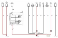
Since the concern was lighting system related, the path taken beyond building the vehicle and entering the Service Manual/Bulletins page followed through Body Systems > Lighting > Headlamps > Exterior Lights Schematics and Routing Systems DRL, or possibly Park Lamps.
There's a couple of options that can be taken, to verify appropriate fuses as would be a preliminary step and quickly review any commonality on the power and ground side of the affected circuits. Nothing was apparently common to both systems from the fused side.
When looking at individual documents, it is time-consuming comparing multiple schematics, so to get a better view of the involved circuits, the following path was taken from the "Service Category" menu: Power and Signal Distribution > Wiring Systems and Power Management > Schematic and Routing Diagrams > Ground Distribution Schematics > Figure 2: G103, G104 and G105.
Selecting the G104 group document, puts all G104 grounded circuits on the same "map" alleviating the need to use multiple documents.
Since GM vehicle electrical system zoning identifies that # 100 circuits are in the under hood electrical zone, reviewing the routing diagram identified G104 as being located in the right front of the compartment, close to the engine mount area. The students verified it as being securely connected, performed a voltage drop at the location with the lights on and found nothing out of specification to suspect and issue with the connection.
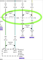
At this point, it was an opportune moment to reinforce the benefit of the CGI viewer. When mousing over or hovering over specific areas on many of the more current vehicle platform schematics, the conductor paths will highlight in red, showing the entire path, much like Jorge Menchu's highly regarded and practiced colouring with crayons exercise. In the case of G104, you will see from the following two photos that not all of the conductors connected to G104 highlight together. [Hover 1 - Fig. 1]
Approximately half of the wires connected to the G104 location remain in black while some are in red. Moving the mouse to hover over a conductor that remained black, now reverses the colours as you can see here [Hover 2 - Fig. 2]
This immediately identifies that there are more than one terminated ground bundle at the G104 location. With the students now clued in, they rechecked the ground stud and discovered only one bundle and ring terminal fastened to the stud.
Searching a little deeper along the wiring harness, they discovered another branch with ring terminal that should have been connected to the stud.
You will recall that the vehicle had "returned from the body shop". The problem was simply that only one ground bundle had been reconnected once the inner panel had been refinished!
In reality, the activity was staged by yours truly to replicate what does occur in the real world and has happened to me, all be it on a different vehicle sent to me from the body shop.
The other benefit of the CGI viewer, was the aforementioned bonus when mousing over components, that results in single or multiple hand symbols, signifying that there are one or more links at these "hot spot" locations.
You will recall that previous to the adoption of the CGI viewer, the "LOC" or "DESC" buttons had linked to the Master Electrical Component list, where the desired component or connector end view had to be searched either by component name or code, depending on the time line in SI.
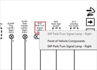
With a mouse click on the component hot spot in the schematic, followed by a second mouse click to select a desired harness routing view or connector end view from the drop down menu that opens, the desired information is immediately linked to directly from the schematic. [Mouse Over - Fig. 3]
While there are many ways to locate information within GM eSI, when time is of the essence, (think 0.0 hr - 0.3 hr) navigation proficiency is important.
There are numerous tips, tricks and methods to use GM SI efficiently in our work and they depend heavily on vehicle platform along with stage of SI development at that time. We can only touch on a handful here, but hopefully there's a useful tip or two for you to try next time.
Regards,
Triggering a PICO Recording With a Scan Tool
Technical Tips Forum
Robby from Alabama
The other day, I had a 2015 F150 3.5L GTDI with a complaint of a CEL. It was setting the following DTCs:
P0365:00-28- (PCM) - (CMP) Sensor B Circuit (Bank 1) P0369:00-28- (PCM) - (CMP) Sensor B Circuit Intermittent (Bank 1)
After clearing the DTCs, I found it quite difficult to get the DTCs to return. I was finally able to figure out that if I allowed the engine to idle long enough, the CMP1_EXH Fault PID would randomly read "Yes":
2015 Ford F-150 Platinum - Fig. 1
Figuring out the cause wasn't that hard. Another tech suggested I swap the Intake and Exhaust CMP sensors and see if the fault followed (fortunately, the sensors are the same). The fault did follow the sensor:
2015 Ford F-150 Platinum - Fig. 2
A scope wasn't needed to diagnose this, but I still wanted to get a waveform of the fault just to see electrically what was going on. The problem with that was the engine might have to idle for up to 2 hours before it would happen. I had IDS set up to "Beep" and trigger a recording when the CMP1_EXH Fault PID changed to "Yes". My next goal was figure out someway to trigger a scope recording at the same time.
To do that, I connected an extra channel on the scope to the computer audio circuit using a line in cord plugged into the headphone jack. I then set up a Single trigger on that channel with trigger placed about midway in the time base. Now, when IDS triggered the recording and "Beeped", the voltage on the audio circuit would trigger, allow the waveform to fill the buffer, and stop the scope. I was now able to walk off and do something else.
Here's what I found:
2015 Ford F-150 Platinum - Fig. 3
Here it is zoomed in:
2015 Ford F-150 Platinum - Fig. 4
At first glance, those spikes on channel B look like ignition, but it's not.
On a side note, I used one computer for IDS and another computer for PICO. Here's a good post explaining why.
Chrysler CAN-C Network Issue
Technical Tips Forum
Morgan from Minnesota
Here's an interesting one we had the other day. The vehicle was towed in as a no crank. The customer also noted that all the lights were illuminated on the dash during KOEO, and the key FOBs wouldn't work.
We performed a code scan and found that only the modules on the Interior High Speed network would respond. I kick myself now, but I missed the opportunity to take a WiTECH screenshot of the inoperative network. Picture something like [this - Fig. 1] but all the modules on the left, connected to the black wire, were colored red because they weren't responding.
For those who may not be familiar, here's a brief overview of how this network operates . There are 3 CAN networks working side by side with a gateway (the Totally Integrated Power Module/ TIPM in this case) as the center hub: The Diagnostic CAN-C, CAN-C, and CAN-IHS. The [Diagnostic CAN-C - Fig. 2] is like your standard CAN circuit at pins 6 and 14 of the DLC, except the network only goes from the DLC to the TIPM, and is only used for Module to Scan Tool communication, the other networks are for module to module communication. The TIPM physically and electrically isolates the buses from each other. The CAN-IHS (Interior High Speed) is for "less critical nodes" (body, radio, etc) and the [CAN-C - Fig. 3] is used for "more critical nodes" (think powertrain, brakes, airbags).
Since the DLC isn't directly wired to the CAN-C network, in order to check terminating resistance you need to check at one of the modules. With the battery disconnected, we pulled off the ABS connector and found over 100 ohms of resistance between the CAN + and CAN - wires. At this point all I know is that it's not close to 60 ohms, so there's an issue.
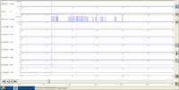
Next, I back probed the network wires at the TIPM and scoped a waveform like this during [KOEO - Fig. 4]. At first glance it appears like somewhat normal communication, but a closer look shows that the bias voltage is resting near zero instead of 2.5. Here's a shot of the [Diagnostic CAN-C - Fig. 5] for reference.
It appears that something is pulling these circuits low, but not low enough to completely eliminate communication attempts. The ABS, PCM, and TIPM are all near each other under the hood, but unplugging them didn't change anything. If you take a look back at the circuit [there's two connectors - Fig. 6] that can be unplugged to isolate those portions of the network. We were already right next to [C105 - Fig. 7] which connects the [Steering, Wireless, and Airbag modules - Fig. 8].
Unplugging C105 restored communication with some of the modules. Plugging C105 back in brought down the network again. In this screenshot [the drop is very apparent - Fig. 9].
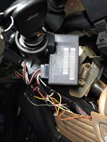
Of the three modules downstream of C105, the WCM and Steering module are the easiest to access as both are mounted to the steering column. Once the column covers were removed it was apparent that someone had had been monkeying around in there. [WCM - Fig. 10]. A [closer shot - Fig. 11] shows that both the CAN + and CAN - wires at the WCM connector have been piggybacked for an aftermarket alarm. Unplugging the aftermarket module let the vehicle start and restored communication between all of the modules. My co-worker said afterwards that the module appeared to have gotten wet and had a nice electrical burn smell to it.
A friend of mine works for one of those very same aftermarkets. He tells me that they'll tap into the bus in order to send Lock, Unlock, etc messages over the network. Maybe for your next no crank no comm issue you might want to consider sticking your head under the dash to look for one of those modules.
Dry Sump Corvette Engines
Technical Tips Forum
James from Florida
Lately, we've been seeing more dry sump Corvette's serviced by oil change and independant facilities with incorrect oil change procedures. Overfilling the oil in a dry sump Corvette can be disasterous and can cause hydrolocking and bent connecting rods in severe cases. If you give oil changes to your least skilled tech, make sure that he knows exactly what he is doing if he services one of these vehicles.
Yesterday, a customer came in with a 2014 Vette with a complaint of smoking badly, running rough and Service Engine light on. He stated that he had his oil changed in a quick service facility and it started smoking soon afterwards. He returned to the facility and they said that the oil was overfilled and drained an undetermined amount of oil from the vehicle. His problems increased and he brought the vehicle in to us for repairs.
I checked the oil level and it was correct. Removing the air intake tubing, I saw it was filled with oil at least 1 inch deep. The air filter and the MAF were heavily oiled and oil was dripping from the air box. The oil in the intake was dirty and did not appear fresh.
We gave the customer a repair estimate (not warranty) and he called the oil change shop who sent 2 people over to inspect the vehicle. They said that they did nothing wrong, just drained the oil, poured in 5 quarts of oil and let it go. I told them that the system held 9.8 quarts and they said that couldn't be since 5 quarts overfilled it and they needed to drain some back out.
On a dry sump Corvette, there are 2 oil drain points. If you only remove the drain plug in the front of the oil pan, only 2 quarts or so will come out from the sub-pan. The rear drain will drain the main pan and the oil tank. It seems that they drained the sub-pan only and added 5 quarts, overfilling the system by 3 quarts. On top of the oil tank, a vent tube leads into the air intake. An overfilled system will vent all that excess oil directly into the intake tubing. That's why the oil still looked dirty, it was never replaced, just added to.
So, be cautious. This was a 600 beans mistake, I saw a similar case on a ZR-1 that locked up the engine and bent 2 connecting rods. That was a 9000 beans mistake.
Electronic Throttle Control
Technical Tips Forum
Jim from Pennsylvania
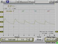
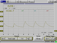
As I'm seeing more and more electronic throttle control issues, also being asked a lot more by techs on if and how to clean the throttle body correctly. I've been doing some before and after waveforms with the lab scope and mini amp probe. In all of the attached waveforms, the mini amp probe is set at 100 mv = 1 amp and the reading in the upper left corner is the avg during the mode. The first wave in both sets of 4 is warmed up at idle, then while turning the steering wheel, then in gear, lastly with the A/C on. The first set of 4 is before cleaning on this late model Mustang and then again after cleaning.
NOTE - this throttle body was NOT very dirty but shows a pretty much lower current draw on this vehicle. BEFORE CLEANING , in the order I stated above Fig. 1 Fig. 2 Fig. 3 Fig. 4 AFTER Cleaning in the order I stated above Fig. 5 Fig. 6 Fig. 7 Fig. 8
VVT Solenoid Pintle Hump
Technical Tips Forum
Ray from Ontario
I have had VVT solenoids on various vehicles where the solenoid pintle is stuck in the on position and the ECM will have CMP, CKP sync codes. This is a good way to see a bad solenoid without removing it. In some engines, you have to remove the intake to remove the solenoid.
I connect an amp clamp to a ground wire and I ground the VVT solenoid to show the pintle hump.
2014 Hyundai Elantra GT, PicoScope Data File - Fig. 1
2014 Hyundai Elantra GT, Waveform - Fig. 2
We Guarantee Your Car Will be Fixed Right, on Time on Budget
Shop Management Forum
John from Massachusetts
We guarantee your car will be fixed right, on time, and within budget.
That is a common statement in the auto repair world. It sounds great, but how realistic is it?
In my opinion, the requirements to complete a job can only be known once the car has been dismantled enough to fully understand what's needed and how much time and material will ben required. The hard truth is, we are in the business of repairing things, and just as in repairing people, there can always be surprises and complications.
Motorists often misunderstand what we can know. For example, we look at a car with worn tires and we say, new tires are $xxx. It seems simple to price out tires, mounting, and balancing. But what if the tires are dismounted and one of the rims turns out to be cracked?
Suddenly we have a $500 complication -- a new rim is needed. We can't put the broken rim back on the car because it's unsafe, and the motorist is left with no choice but to buy a new rim.
Most shops would have quoted a set of tires without any tear-down at all. And they would be very likely to have a customer relations problem when the broken rim was discovered. This is not a common occurrence -- 99% of tire repairs proceed smoothly. But it can happen.
The question is, what do we do about it? In my opinion we start by setting the correct expectation. We tell people that tires are $xxx, but there could be surprises. The rim is one example; as cars get more complex the service complications become more numerous and more common.
You don't get a promised cure at a guaranteed price at the doctor's office. Why is car repair different? It's not, but people mistakenly assume it is. To a large extent that's because mechanics set unattainable expectations and then they allow themselves to be painted in an unfavorable light for not living up to an impossible standard.
The way we correct that is by being clear what we can control in the offered service, and what we can't. Tires are a commodity; we can quote the price for different brands. Mounting is a standard service too; we can quote time to mount tires on the rims we see. Most of the time, that's all that's involved in a basic tire job. But when we give the motorist those figures we have a duty to inform them of the possible complications. Some will say, what's the worst case? That's impossible to answer most of the time. In medicine the worst case is, you die. In car repair the worst case is, you need a new car.
99.9% of the time those dire complications never come to pass. But people get old and die, and so do cars. The outcomes will not always be good. The best we can do as service managers is to disclose what we can, and paint a realistic picture.
Doesn't the customer always have the last word? That can be a misconception. Take the example of the broken wheel rim. Once discovered, we cannot undo the discovery. The customer may say "put it back like it was" but we can't. The forces to mount and dismount the tire may turn a cracked rim into a cleanly broken one. There may be no path but forward, and the only choice the motorist has is to buy a new or used wheel rim. Using the rim he arrived with may simply not be an option.
We may take one thing apart for repair, only to see another broken thing beside it. If that broken thing is a possible safety hazard, we place ourselves at risk if we do not fix it, so the customer in that case does not have the ability to decline a repair that would compromise safety. They can of course halt the whole job and tow the car away, but that does not do them much good. The newly discovered safety hazard becomes part of the current repair cost, no matter who does it.
The only options then are abandoning the car, fixing it now, or fixing it later. At one time cars were simple, and "fix it myself" was an option for many owners but with today's need for dedicated test computers and special tools it's a rare owner who has that option.
Here's the hard truth: Taking a car apart to evaluate damage may render it inoperative until fixed. Hospitals warn patients in advance when they undertake risky procedures. Those of us in the auto service business have a responsibility to do the same.
Another common situation is the multi step repair. Here's an example: A car comes in with an inoperative oxygen sensor, and the check engine light is on. We see the failed sensor and replace it. A week later the light is on again. This time the newly repaired oxygen sensor is sniffing an out of range condition, and we repair that next. It was not possible to see repair #2 without the prior completion of repair #1. Whenever we repair engine lights we always warn motorists that more than one round may be needed because there are a thousand things that can illuminate that simple light, and they may reveal themselves one by one.
If this sounds complex, costly, and scary, I agree! Yet it is the world we live in.
From the shop's perspective, our duty is to keep our training up to date and make sure we have the latest tools for the jobs we undertake. We need to use our best abilities to diagnose vehicles, and report our findings promptly and clearly. We need to be at the top of our game, and do our level best to get good outcomes. At the same time, we have to be clear to our clients with respect to what may go wrong and why, and what we can do.
Cars are complex and service is specialized. Not every mechanic can fix every car. In a big shop like hours there are techs who specialize in certain brands (like BMW,) and others who specialize in certain procedures (like convertible tops.) Knowing what we know, and what we don't, is always a challenge and an exercise in humility.
Corvette Class 2 Communication Failure
Technical Discussion Forum
James from Florida
Usually I post more complex repair procedures. Lately, I've been trying to submit less complex problems for those of us just getting used to data communications problems. This is an example of such.
A 2011 Corvette came in yesterday with the complaint that the key fob was damaged by closing it in the door and wouldn't work at times. The customer had only 1 fob and wanted it replaced with a new one. I pulled a new fob from parts and tried to program it to replace the #1 fob that was damaged. If you don't program a new fob on a Vette to replace either the existing #1 or #2 fob, it will program into position #3. It will still function normally but personalization functions will not be enabled.
The new fob would not program as the RCDLR would not respond. Doing a fast scan check, I saw all the class 2 modules were unable to communicate although all the GMLAN modules communicated normally. The high speed modules all had multiple U codes set as current and history.
My first diagnostic step was to check the Class 2 bus resistance...
2011 Chevrolet Corvette, Fig. 1
I don't see a problem inhibiting communication there...How about the bus voltage?
2011 Chevrolet Corvette, Fig. 2
OK. Here's our problem...excessive voltage on the bus, but from where? Usually this is caused by a module leaking voltage onto the bus, but which one? I saw a clue staring me in the face...
2011 Chevrolet Corvette, Fig. 3
An aftermarket Pioneer Nav radio has been installed. We have many problems with aftermarket components either causing communication problems or key off draws. Since the JX 208 bus connector is easily accessible under the R.F. access panel, I pulled the comb, opening 1/2 the bus that the radio was on. That restored communications with all the Class 2 modules on the JX205 bus connector. Assuming a radio fault, I backed out terminal C, leading to the radio, from the JX208 connector and reinstalled the comb. Let's look at the voltage now...
2011 Chevrolet Corvette, Fig. 4
That's more like it. All communications are restored except for the radio and I was able to program the new key fob without a problem.
GM HVAC Blower Motor Technology Changes
Technical Discussion Forum
Martin from British Columbia
Reading the thread below related to the melted HVAC blower motor connector, moved me to post about changes to GM blower motor technology, that at least for GM pickup models was introduced in the new body style 2014 models.
It seems that the DC brushed electric motor has been around forever and for whatever reasons, GM engineers have moved to adopt brush less AC motor technology. We can debate why, but eliminating the annoying ticking of brushed motors at low speed is reason enough.
With sensitive electronics susceptible to EMF and HFO-1234yf refrigerant soon to be widely adopted as just a couple reasons worthy of consideration, I'm sure that there are other reasons we might think of other than keeping the engineers busy! VBG.
So, when a student brought an HVAC blower motor to class from a 2014-2015 something GM pickup truck that had been replaced due to submersion in water, we "Curious Georges" could not resist the temptation to take a look.
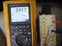
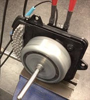
The traditional design "squirrel" cage or "hamster" wheel that was pressed on during manufacture, was removed for better viewing and the module cover on the back side removed to reveal the controls board and 3 phase connections. What remains is the AC motor. The stationary 3 phase windings can just be seen in this view, Blower Motor 1 - Fig. 1 along with the module heat sink. The control module and basic connections for a simple bench operational test are shown here. Control Side - Fig. 2
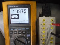
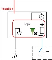
Here Blower Control Logic - Fig. 3 is a "down and dirty" re-creation of the basic circuit using the bare minimum to operate the motor through a fused B+ jumper and B- to the main terminals of the module and connecting our trusty Kent-Moore signal generator Signal Generator - Fig. 4 to the control circuit to replicate HVAC control signal inputs to the blower motor logic module.
Increasing the duty cycle lowers the motor shaft RPM and conversely, decreasing duty cycle increases shaft RPM. The motor is almost silent and very powerful. With a strip of photo tachometer tape affixed, I seem to recall around 4000 RPM being measured.
Of course, with the change in technology from DC or AC, comes some revision in diagnostics. The AC motor does not allow for traditional "bench testing" through connection of power and ground to the older, most basic of DC blower motors.
Regards,
Finding Battery Draw with Thermal Camera
Tool & Equipment Forum
Roger from Alberta
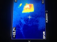
Well I figured I would post these pictures, it works. I read a while back about thermal cameras and ended up buying a FLIR E5 thermal camera probably year or so ago. We mostly have used it for bearings on drive lines and engines. I remembered reading some one using it for battery draws. I actually have used it twice in a couple weeks for draws.
The first one ended up being a alternator which was pretty quick find. I usually make sure the vehicle has sat over night so its cold [relatively same temp in/out front to back] and give a quick look with camera. The alternator stuck right out. Know yesterday I had a 08 dodge 5500 that has a dump deck and is highly modified for oil field. 90 ma to 100 ma draw. So this morning decided to get camera out and within about 5 minutes had my draw [auto shut down for engine over rev limiter].
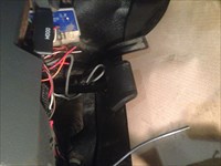
Here is the pictures from under the dash with thermal camera and iPhone. Unplugged module and we went from 95 ma to 20 ma. [Thermal camera - Fig. 1] [Thermal image - Fig. 2]. I would not suggest go out and say buy one because its going to be the go to tool because I must admit we have only used it a handful of times. This is the one time I could say it defiantly helped.
| |