|
Staying up to date with industry trends is one of the many advantages one can achieve by participating on iATN. Given all the variables that exist in today's vehicles, electronics, mechanical changes and what-not, you're bound to run into a symptom or system failure that simply falls outside of what yesterday's logic dictates. This issue of the iATN Review includes several such articles. I've been in the industry for three decades, and I discover something new and interesting being discussed on the network on a weekly, if not daily, basis.
Another benefit that comes with your membership is the opportunity to network with fellow professionals sharing similar challenges. When you attend a professional event, training class or meeting, you'll have the opportunity to meet face-to-face in the hallways with fellow iATN members, knowing that you can continue your discussions later on iATN. I count myself fortunate to be able to attend many such events throughout the year, and always look forward to meeting both new and long-time members.
In this quarter's Review we're highlighting discussions about diagnostic techniques used to solve for P0420s and exhaust leaks, programming anomalies on a 2012 Ford Focus, experimenting with vacuum and compression waveforms while manipulating valve lash on a Honda, how a shop owner's daughter saved the day, a positive story about ASE & Prometric, a diesel exhaust fluid analysis that includes an awesome pictorial, a Cummins 5.9L with coolant in the oil (that isn't from a leaking head gasket), and finally, a nice tip on how you can swap out the key blade when replacing fobs on late GM vehicles.

Scott Brown
iATN President

2014 Caprice P0455
Technical Tips Forum
James from Florida
I had a 2014 Caprice police special with a 6.0 come in today. The vehicle was ready for delivery but the MIL was on. Scanning with GDS2 showed a p0455 set current in the ECM. Checking data, there was no PID for fuel tank pressure available. Proceeding to EVAP Output Control, there was only an option to control the purge solenoid but no control of the EVAP vent solenoid and no purge/seal procedure available.
A quick visual showed a tight fuel cap and all visible lines attached firmly. The EVAP cannister and vent valve are in a similar position to the Camaro but less accessible if that can be believed. Since I can't command the vent solenoid closed, I can't test the EVAP system with smoke or nitrogen. I can't read the fuel tank pressure sensor so I don't know if there really is an EVAP leak present. Now what?
The version of GDS2 was the most current available. Since GDS2 reads the VIN, it automatically enters the type of vehicle that you're working on. How to fool it? If you go to the first diagnostic screen and remove the VIN and put number 1 in the block and hit enter, you will be directed to another screen that lets you manually enter the vehicle type. I entered the vehicle as a 2014 Silverado with a 6.0 and my missing PID's and functions appeared. Normal diagnostics then showed the problem to be a failed vent valve that would not close.
A Hidden Parasitic Draw
Technical Tips Forum
Andrew from Utah
Parasitic draw testing can be one of the greatest challenges that we face as technicians. Sometimes when the battery goes dead overnight and only a minimal draw is present on the vehicle it is assumed that the draw is an internal short in the battery. But is it?
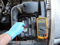
Acid on the exterior of the battery can create a conductive path between the battery posts. Amperage draw is not able to be measured by any traditional means. However there is an easy test that can be done. The battery case itself is not supposed to be conductive so if you are able to read any voltage anywhere on the case there is current flow occurring. [Current flowing on battery case]
A thorough rinse of the battery and finding the cause of the battery acid coming out will bring this draw to a quick halt and keep it from returning.
Understanding Alignment Angle Changes
Technical Tips Forum
David from Michigan
Recently I was asked a question by a younger Tech that made me think. The thought was a realization, that there are probably many young Tech's out there, that don't understand how Caster angle affects Camber angle, when you steer a tire away from the Toe angle's specification position.
If Caster is 0 Deg, then Camber does not change when you steer the tires from right to left. But, Camber changes when the tires move to the left or right, anytime Caster has a value greater than 0. The higher the value, either + or -, the more Camber will change as you steer the tires away from Toe in Spec. Position. So it needs to be understood, that you are not ever to set Camber on a wheel, unless you first check Camber on that wheel while it is in Toe Spec. position when the Camber is checked.
The Caster changing Camber relationship is not much of a problem on most vehicles. But, it is very important on vehicles that are set with very high Caster. You better understand this concept should you decide to align any vehicle with over + 5.0 Deg. of Caster.
So if you start on a alignment, on a vehicle with high Caster, and the Toe is way out of specification, it is better to adjust toe into the ballpark, before you consider if this vehicle actually does need to have Camber set. The most common reason a vehicle ends up on the rack, is having had parts changed. Some Techs don't have the skills to get them installed "in the ballpark". The new tie rods adjust quickly, so just move them and get it close.
What I have seen happen, is a Tech will adjust Camber first, on a wheel that is not pointing straight. The Inaccurate Camber angle they see on the screen actually could be, "in spec", IF they checked it, with the wheel straight ahead. They adjust the Camber first, then they adjust the Toe angle second, and then find the Camber went out of Spec. as they moved the tire to straight ahead. Then they end up doing the whole routine over again until finally it is right. I actually watched a guy years ago, align a car in circles, for almost two hours because he did not understand this concept. The vehicle was a Euro with a Caster Spec near +10 Deg, and Camber tolerances that were very tight.
You don't have to do, Toe adjustment first on all of them. You can steer the wheels individually to Toe in Spec., and see what the Camber is on each wheel, one at a time. But, be warned that on some vehicles, if toe is way out, the vehicle will not be sitting correctly level because the excess Toe will affect the way the vehicle is loaded, when one tire is straight, and the other tire is turned a few degrees to the side.
Vehicle stance affects the Camber angle you see on a wheel, not just from having one tire only turned, but it also is changed from reality, when the Camber is drastically out on the opposite wheel of the same axle. That is why you will see Camber change, on a wheel opposite of the one you just adjusted. After moving a L.F. wheel 1 full Deg., after Mac Struts were installed for example, you will notice the R.F. will often drop a couple of tenths lower. This is because of load change. It is always better to adjust alignment angles first, on the side that is most incorrect. Sometimes, the other side will fall into Spec., and save you some time.
Understanding the angle to angle relationship, and how Toe being drastically out of Spec. affects the reality of where Camber really is at, is helpful to getting the alignment to correct faster, when you get one on the rack that is in "outer space" as a starting point.
P0420 and Exhaust Leaks
Technical Tips Forum
Mike from Ohio
Over the years I have learned many great things from the iATN gurus. The P0420 testing tactics have evolved over the years and have morphed into a pretty simple trouble tree. The Input of many people way smarter than myself seem to agree on a few easy steps. One of them being the presence of exhaust leaks. As you already know some exhaust leaks are rather hard to find.
Using a tactic I took from a less than great class seems to be a real blessing to me. This class wasn't all that bad as I took this tactic away using air pressure to search for exhaust leaks.
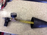
I'm using the exhaust cone from a redline smoke pro and a simple regulator that I usually dial in at 10 PSI. It seems I have found more exhaust leaks and hence fixed P0420 codes in the last year than ever before. Its very nice because you don't get burnt by hot exhaust and seems to really make this task very easy.
Exhaust leak tool
This may have been brought up already and If so I apologize =) If you have not tried this you really owe it to yourself to try it.
Today's Mistake - Factory Mode
Technical Tips Forum
Michael from New Jersey
Shop requested programming for new replacement BCM on 2012 Focus. I downloaded the configuration from the old BCM, and loaded the new unit. Programming was very different than usual Ford programming. The dash did not light up until the programming was 90% complete. A little disconcerting at first glance. At the end of programming, a message on the laptop screen with final instructions; the last being to follow online directions. All codes cleared, I set the TPMS, vehicle started 8 times. Looked good to go, so I left for the next job.
45 minuted later, I get the call, Focus will not consistently start, remotes do not always work and no dome light. No codes pulled, I must return to check this vehicle.
No problem, hook up the IDS, there are 4 communication codes; 2 abs, pcm and tcm. I reprogram the pcm and tcm, clear codes and start car 10 or more times. BUT the message center reads "Factory Mode". ASSUMING that the message pertains to customer choices in the BCM, and seeing no codes, I hope that I have finished. 5 miles down the road; the same call, "No start".
I realize that all my testing/starting was done with the IDS attached. No IDS, no start. Now the tech sees the "Factory Mode" message and goes to the shop's information system for an explanation. Not sure how/why the vehicle got reprogrammed into the "Transport" mode, or "Factory" mode. A simple procedure, key/brake/hazard switch, placed the Focus into "Normal" mode.
There are instructions in the oasis system; but no mention in Identifix nor IATN. Yes, there were 4 U codes; but no other mention in the IDS. Nor did I see any other online instructions.
Last week I was asked how long have I been programming cars. My answer, "long enough to make every mistake twice". I do not think I will make this mistake again.
Vacuum and Compression Waveforms
Technical Theory Forum
Robert from California
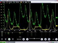
Well I took a little time to experiment with vacuum and compression waveforms on my personal car. I used a homemade vacuum transducer using radio shack parts, a Pico pressure transducer and a PV-350 for the Verus screen shots. I was wondering if I could tell it the valves needed adjusting or not. So I took a compression waveform and a vacuum waveform while doing different things with the valve adjustment. First I tightened the valve lash to zero on #4 Cylinder exhaust valve. This is what I got: [2000 Honda Accord EX, Engine/Propulsion Waveform]. Notice the pressure spike in the intake when the intake opened and the valve overlap.
I then wondered what it would look like with all the exhaust valves tight. This is What I got: [2000 Honda Accord EX, Engine/Propulsion Waveform]. Notice the 5 volt swing of the Vacuum transducer. Also notice the higher running compression reading of a little over 90 psi. Extra exhaust volume raised the pressures.
I then tightened the intake and exhaust valves to zero lash. This is what I got: [2000 Honda Accord EX, Engine/Propulsion Waveform]. Notice it had about a 5 volt swing of the Vacuum transducer. The engine would barely idle with the valve like that. The running compression was about 90+ PSI.
I then Adjusted the valves to spec. This is what I got: [2000 Honda Accord EX, Engine/Propulsion Waveform]. Notice that the vacuum transducer only had about a 3 volt swing. Running compression was only about 65 psi.
If all the valves are the same out of spec, the only way you will know for certain there is a problem is if you have know good vacuum waveforms. If one valve is bad with adjustment or leaking I think you would be able to see it and with an overlay to determine which cylinder.
I thought it would be great on the Honda V6 engine to see if it needs a valve adjustment when they have misfire codes but they run good in the shop. I can upload the whole file if someone wants to look at it.
A Thumbs-up for Prometric
Industry Issues Forum
Gary from Colorado
I took my L1 recert yesterday and things couldn't have gone worse. Last week was super busy and I developed a bad head cold and allergy condition. Since I don't do emissions testing in my area, I bought an L1 prep booklet for $40 that was marginally helpful on I/M, but didn't have much time left to study it.
Sunday night didn't go well and I got only four hours of sleep. So I got up 5:30 Monday morning, had breakfast, took a hot bath, and drove 100 miles to the Prometric test center. When I arrived, I was wishing I had cancelled.
Nevertheless, I found the folks at Prometric to be courteous and accommodating. An older man and lady signed me in. Obviously, everything I had in my pockets, even my handkerchief, had to go into a locker. I was allowed to keep my asthma inhaler and a packaged wipe for my eyeglasses.
I didn't find the checkout with the magnetic wand to be intrusive. But while these kind folks went by the book, they also supplied me with plenty of tissues to take care of my runny nose and didn't mind me taking several potty breaks in the process.
As far as I'm concerned, the computer-based test is far superior to the paper test. I was in a small, quiet room by myself, which is much better than sitting in a dinky high-school desk along with 20-30 other sweaty, dirty mechanics on a hot spring night in a non-air conditioned room. Which, of course, is how I've been doing it for the past 41 years.
As Albin Moore said in another forum, the L1 is experience-based and you can't fake it. Since I don't do emissions repairs and I/M testing, I missed 4 questions in those areas. But I scored nearly perfect on the drivability portion with the exception of a question on APP testing. Looking back, I think the answer was to be found in the Composite Vehicle Manual. Otherwise, the question was simply too vague. But I'm not sure I missed this question, either.
Myself, I think ASE testing is an excellent opportunity to see how one ranks against the industry as a whole. Right now, I can see I need to work a little more on emissions-related issues.
I've always considered ASE certification to be a standard credential for an automotive technician. I don't believe in the idea of a person being a sharp mechanic while not having the reading comprehension skills needed to pass an ASE test (or read a shop manual, for that matter).
Enough of the Fairy Tales. If a person can't understand the simple language of an ASE test and doesn't have the logical and critical thinking skills to solve a typical diagnostic problem, I don't see him having much future as an expert mechanic.
In any case, I'm giving a big thumbs-up to ASE for devising an excellent experience-based test and to Prometric for accommodating a sick, grouchy old Senior Citizen mechanic who should be retired but is too hard-headed to quit...
Low Injection Control Pressure (ICP) Making Life Interesting
HD/Fleet Forum
Ryan from British Columbia
I just wanted to share this on iATN as I feel that I have not contributed much lately. The above truck was brought to us from another shop that found a low ICP concern. The truck shut down on the customer and would not restart until it cooled off. After that it would only run for several minutes before stalling again. A pretty straight forward issue on a 6.0L.
First, I scanned the PCM and found a low ICP while cranking code. The oil level was good but the oil was dirty. So, I flashed up the truck and watched the data stream. Right away the IPR duty cycle is a little high at 30% but the engine was cold. Within 2 minutes it started to climb to 85% and was unable to match the desired ICP value. Shortly there after, it stalled.
With the ICP sensor in the HP pump cover on a 2003 engine, I removed the left valve cover and performed the air pressure test. Right away I could hear a leak internal to the engine with the IPR closed. The air leak could be heard loudest from the oil filter stand pipe. From my experience this indicates a damaged piston-block in the swashplate pump such as this.
[2003 Ford F-350 Super Duty Lariat, Engine/Propulsion Photo]
The IPR had some small metal debris in the screen and the ICP sensor was leaking though the sensor bias was still good. So, I quoted the job with HP pump, ICP, ICP pigtail, IPR, oil change and all needed gaskets. Also, I would change the reservoir screen under the oil cooler. The quote was approved and the work began.
With the truck back together is started right up. I idled it for a while and watched the IPR duty cycle. It was still a little high but the system did have air in it. Unfortunately, this was not the case. The IPR duty cycle started to climb once again. This time though it did not stall but ran at 85% all the way up to operating temperature.
Great, off comes the left valve cover again and more air pressure testing but no leaks were found. I rechecked the IPR screen and tested the electrical circuit to the IPR, all were good. An interesting note is that the IPR % shown in the IDS data logger is not actual duty cycle. At 95% commanded, I saw 64% on the signal, much like a 7.3L. Next, I blocked of the left rail and cranked. Okay here is the interesting part, pressure went up to 1100 psi when 2300 psi was commanded but on the next crank I could only get 360 psi. After sitting for a while the same thing would occur, enough pressure to start and then 360 psi on the second crank.
At this point I started second guessing myself. I know the original pump was bad and under closer examination I found the drive shaft seal had blown out of it. I used a Bosch Rexroth pump which is the OE unit. Did I miss something on installation or did I get a bad pump? Base engine oil pressure was good so it wasn't a supply issue as pressure is measured virtually in the reservoir. My next move was to test the flow of the HP pump. I measured 240mL/10sec of cranking, which is a very good reading from my experience. Generally, 160mL area will barely run the engine.
Knowing that I was only pressurizing the system to 150 psi and my issue was at 360 psi or 1100 psi, I removed the right valve cover to block off that bank. With just that bank blocked off pressure spiked to 3600 psi and settled down at the desired 2300 psi. Was it an injector leaking, the STC fitting or the rail itself? Well it was a mess. The oil rail was loose. There were stripped bolt holes and broken bolts. The last mechanic under here had created quite a mess over torquing the hold down bolts and tried using longer ones (of a lower grade) to patch it together.
With this repaired the system has no problems building pressure. Now I know using nitrogen at a higher pressure would have found this problem but I just wanted to share in my fun for the week.
Daughter Rescues Dad
Shop Management Forum
Mark from Ontario
When my daughter was young, she once got stuck climbing a tree, so I helped her down. It was a simple thing for me, but to her I was a hero. As she grew older I would always help if she fell off her horse or locked her keys in her car. Now she is a grown up young lady in her 3rd year of law school and doesn't need my help for much.
A short time ago I received a large legal envelope in the mail. The letter was from a Trustee in Bankruptcy informing me that one of my large fleet customers had just declared bankruptcy! I checked on the amount they owed me, ($57,000 ) and my stomach turned to ice.
The documents stated they had 10 million in receivables/assets but owed 30 million. Their bank was a secured creditor for 10 million, with the next 20 million owed to over 100 unsecured creditors. I wasn't the only one who did not see this happening.
At supper that evening, I explained the situation to my wife, who was not impressed. My daughter overheard and spoke up.
"Dad", she said, "Under the Repair and Storage Liens Act of the Personal Property and Security Act, I can register liens against all the vehicles you are owed money on".
Before I knew what was going on she asked me for VIN's and dollar amounts. Next she jumped online on her fancy laptop and logged on to the Attorney Generals website. After typing furiously for ten minutes she asked for my Visa # and said that she just registered liens against 15 vehicles from my customer's fleet.
The next week an employee of the Trustees in Bankruptcy called and said he wanted to "negotiate" with me to release the liens. He invited me to a meeting at their offices.
I knew they wanted to put the vehicles in a dispersal auction but the auctioneer had refused to accept any vehicles with liens.
I went to the meeting properly attired in my work boots and coveralls, with the statement of account on one crumpled piece of paper in my chest pocket.
The two trustees sat at a long dark boardroom table, laptops spread out all over the place. They wore nice suits. They smelled of man perfume. I smelled like diesel smoke.
They quickly got down to business and offered $30 K right away if I would release the liens. Not acceptable, I said, since I consider myself a secured creditor. I asked for $50K. They came back with an offer for $40K.
We were engaged in a high stakes poker game and I was not sure just how far to push. I told them to come up a little more and we may have a deal. We agreed on $43 K which was 75% of the amount owed. We shook hands and a few weeks later I got my cheque. I considered myself very lucky and felt bad for the other unsecured creditors who would get nothing.
The business lesson is to watch your receivables.
The life lesson is to always rescue your daughter.
Fun with Diesel Exhaust Fluid
Technical Discussion Forum
Martin from British Columbia
Recently, the specification values provided for Diesel Exhaust Fluid (DEF) in GM eSI were questioned, specifically as related to this thread by Paul Johnson.
The post and ensuing thread discussed possible reasons why a DEF system pump failure was not covered under the vehicle manufacturer warranty, because the recorded value for the vehicle was far below the specifications for DEF and the system was considered to have been contaminated with water.
Of concern was testing methods and accuracy, what equipment was used, whether the technician knew how to use it and why the cost of repair might have been customer pay on such a low mileage vehicle.
Rather than focus on the possibilities of honesty/dishonesty or competency/incompetency which are quite plausible, the real interest was how the numbers were achieved and with what tools and tests. There are on-vehicle systems tests to run when DEF quality issues are identified, but the concern of what hand-held tools are generally used in a GM dealership arose.
Having graced those service bays for many years, I am quite familiar with most of the tools that have been around for some time, although correlating exact tool numbers can be a little difficult without a full description.
Of particular interest, was the fact that GM specifications in eSI, listed the acceptable range for DEF as 1.310-1.3843 @ 20° C (68° F). Since pure water is identified as being 1.3330, there was definitely some confusion.
Reviewing DEF specs from a number of supplier sources, confirmed that pure DEF specifications have a Refractive Index range of 1.3814-1.3843. I had encountered this some time ago, when the measurement issue was discovered, by another instructor and the numbers didn't jibe, but I didn't pursue it any further than making a mental note. It seems that when using refractive index to display specific gravity there is some difference that is just beyond my need to research further.
So, I sent a memo to my GM contacts that quietly founds its way across various brand quality managers desks to an individual charged with investigating. The results of his research, supported a change in the listed specifications for Duramax and Cruze diesel application documents in eSI this morning. Since eSI documents are live, updates can be effected quite quickly, often within 24 hours.
Fast forward to the end of my work day this afternoon. Armed with the Leica refractometer from my program which was exactly the same model as supplied to the GM dealership where I worked for many years, I stopped in at the GM training centre to gather more information to hopefully better understand where the errors or anomalies in the specifications arose from.
Since I also discovered that there were also anomalies in the ratio of de-ionized water to urea in SI, reference to the actual percentages of de-ionized water to urea has now been deleted.
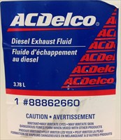
I had the opportunity to measure this ACDelco supplied DEF [Yara DEF] used in the Duramax course and also some YARA DEF. The latter fell off the back of a truck, quite literally and was picked up off the highway by my co-worker. [YARA DEF] [Yara DEF].
The plan was to gather information by measuring both DEF samples using the Leica refractometer, Reichert refractometer and the Kent-Moore supplied Adblue DEF refractometer to compare readings in an effort to make sense of the numbers.
First things first, exploring these refractometers brings to my attention that the Kent-Moore refractometer [Samples for testing] has an AdBlue Urea scale, with a waterline set at 20 ° C and a scale that reads from 15% to 40%. Sorry, it is near impossible to take a photo of the scale. There are plenty of sources for images of the DEF refractometer scales.
Hmmm, none of the testing in eSI lists testing using the percentage scale. This refractometer was supplied for training. I didn't see anywhere in diagnostics any range for urea. The only range reference had been the values in question.
Reading about refractometers versus specific gravity testing of various fluids (relative density), appears to identify that there is some variance in values. Searching the Internet, I discovered that there are specific gravity floats available for just about any imaginable fluid. I'll keep this in mind later during testing. I'm simply attempting to identify if and where the error is.
Testing all of the refractometers to ensure calibration accuracy at 20° C in my home kitchen science experiment this afternoon yielded accurate calibration to the water lines, using the calibration de-ionized water sample "D" in the temperature controlled environment. [Temperature] Outside temperature value was in the kitchen.
Since Paul Johnson had wondered what the differences might be between tap water and de-ionized water, I included a couple of extra samples.
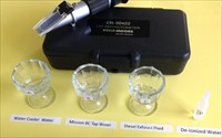
So, over to the kitchen table , set up with the following samples in clean glass egg cups, were Exhibit "A" from our kitchen water cooler (sorry, I couldn't resist the pun) , Exhibit "B" Municipal tap water, Exhibit "C" YARA Air1 DEF and Exhibit "D", the de-ionized calibration water from the Kent Moore DEF refractometer kit.
Prior testing of both the ACDelco and Yara DEF samples had resulted in identical measurements of exactly 32.5% to specifications. So, for this test exhibit "C", I used the Yara DEF. So, it appeared that when tested with the DEF refractometer, the sample met specifications exactly.
Since the Leica and Reichert Battery and Coolant refractometers tested both the same, the Leica was used for the tests. All of the water samples tested exactly the same, to the calibration line, including the Kent Moore DEF refractometer water line.
Testing DEF using the Leica refractometer yielded 1315 which might possibly support why the GM eSI specification for DEF was originally listed as 1.310 -1.3843. Note: On refractometers used for specific gravity measurements, it is very common to leave the decimal place out for ease of viewing. so, 1315 = 1.315, which is not far from the specification previously listed at 1.310.
So, I now wonder if when DEF was first tested using a refractometer, if one of these battery and coolant refractometers was used, resulting in the lower specified number in eSI, than that of the DEF manufacturers. My result with the Leica was also backed up by the same measurements on the identical model Reichart refractometer.
After all of this, my conclusion is that to be sure of DEF quality using a hand-held tester, to use a DEF specific refractometer that indicates % of urea, not a common battery and coolant refractometer. Depending on how much one is willing to spend, DEF hydrometers can be purchased in the traditional float style hydrometer, analog refractometer as used in this post, or digital.
I would like to test DEF using a dedicated float type DEF hydrometer and if available, a refractometer specifically identified for DEF measurement, because my suspicions are that the battery electrolyte specific gravity range does not provide sufficient accuracy when using a refractometer that is not dedicated to testing the specific fluid.
I suspect that since the SG value achieved on the Leica was so close to the original listed DEF specs in SI, that this tool was possibly originally used to identify that value. Just my opinions, based on the numbers achieved multiple times using clean containers and test instruments. Looking at combination refractometers that can be used for DEF, coolant and battery electrolyte testing, each as its own dedicated scale. Food for thought.
At the end of it all, even given any inaccuracies in the measuring tool used, achieving the 1.295 value by the service technician would support an excessive ratio of water to urea.
An Electrical Ghost Finally Found
Technical Tips Forum
Dale from North Dakota
I don't normally do Ag machinery service calls but when it's one of your best "Just fix it, I don't care what it costs" customers, well, you make exceptions.
The machine was a John Deere 8960 articulated 4wd tractor that the customer had bought brand new in about 1990. The reason I was there fixing it was because a wire harness that runs from the cab to the rear of the tractor had gotten tangled up in the center drive shaft. The customer had spliced the wires but couldn't make the hazard and turn signals at the implement connector work. That fix was easy enough as he had a few wires flipped around and didn't see two more wires that were damaged. Sorted out the wiring and re-secured the harness to keep it away from the spinning drive shaft and all was well.
As I was finishing up the owner asked me if I would check the charging system since they had added some more field lights and wanted to be sure the alternator and the 3 new batteries were up to the task....So I hook my voltmeter up to the center [handiest] of the three 12v batteries and with the tractor running I find only 12.30 volts. Hmm, not good. I go to the alternator stud and find 14.44 volts. I move to the starter lug and still find 14.44 volts. Go back to the battery and find only 12.30 volts. What the??? This thing has BIG battery cables that are in great shape and connect the 3 batteries in parallel so it's like one giant 12v battery. Next I start checking for voltage drop...thinking maybe the positive cable has a bad spot hidden somewhere under the cab but get essentially zero voltage drop...but still the battery is reading only 12.30 volts. I do a voltage drop on the ground cable...zero again. Now I'm really perplexed and the customer is telling me that since this tractor was new they've had lots of problems with slow cranking in cold weather and battery failures. While it was under warranty the dealer tried different alternators, batteries, and a starter. In the years since it became one of those tractors that you might have to jump to get up enough cranking speed for it to start if it was cold out.
So I check the actual cable to post connection and find nothing but perfection. I load test each battery by itself...all good...except the middle one needs charging. Finally with everything hooked up and the tractor running I was rechecking voltage and happened to check the first battery and find...14.40 volts. Check the second battery again...12.30 volts. Check the third battery....14.4 volts. Aha! I do a voltage drop between all the positive post cable clamps and find zero. Do the same on the negative side and find a drop of about 2.10 volts at the middle battery cable clamp.
Turns out that when the cable was produced and installed when the tractor was NEW there was almost no contact between the copper wires and the center of the three cable clamps that attaches to the center batteries negative post. This meant that the center battery...which I randomly hooked onto while testing...wasn't being recharged and wasn't contributing to the cranking power during cold weather starts. There was just enough of a connection, about 180 ohms of resistance, that when the tractor sat long enough the discharged center battery could slowly siphon off power from the two fully charged batteries.
To avoid having to dig out the entire big cable to repair the problem we installed a short jumper cable between the center batteries negative cable clamp pinch bolt and the ground lug. Bingo! No more voltage drop and an instant and noticeable increase in engine cranking speed.
I might have had to scratch my head longer on this one but I had run into a similar situation years ago where an older 6 volt tractor of my own had developed a slow cranking problem. To fix it I had converted the system to 12v negative ground, changed over the ignition system, replaced all the battery cables only to find it only cranked over just a wee bit faster after all that work. The battery tested out good as did the starter and all the connections. It charged at 14+ volts, but was a slow cranker. If it was really cold you'd have to add a jumper [and we'd jump it at the easy-to-get-at starter terminal] to get it to crank fast. One day when it was in the shop I had the battery cover off and it was cranking slow as usual so I grabbed the jumper pack to jump it at the battery and for some reason accidentally touched the positive battery cable clamp with my thumb and immediately discovered it was hot enough to instantly blister the skin. What???. I Dissected the "new" cable clamp and found that despite being and looking brand new there were only about three strands of wire actually fused into the cable clamp. Enough connection for the battery to stay charged but not enough to fully power the starter. A new cable fixed the cranking problem instantly and left a good lesson in it's wake.
Long story short, voltage drop tests are worth their weight in gold and remember to test EVERYTHING even when it looks or is new. You might be surprised at where you find the problem.
Thermostat Diagnosis Using a Pico Scope
Technical Discussion Forum
Michael from Auckland
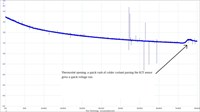
Just finished a diagnosis on a 2002 Saab 9-5 with a 2.0L spark ignition engine. I'm a mobile tech and attended a call out for a check engine light on. Performed a diagnostic scan had a P0117. Customer states vehicle has not over heated. Firstly I started off by checking there was sufficient coolant in the system, and a quick look at some service history shows the system had a flush at a SAAB dealership approx a year ago. A brief visual inspection of the resivour cap, all looked alright. With the engine cold i performed a pressure test, no leaks found.
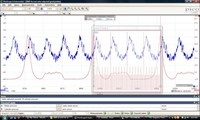
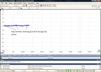
So out comes my good friend the 2 channel Pico scope. Channel A connected to ECT sensor signal wire and channel B connected to ECT ground. As you can see from the waveform attached as the engine reached operating temperature and the thermostat opens a quick rush of cooler coolant flows past the ECT and the voltage momentary increase. In the other waveform I am snapping the throttle and as you can see the voltage rises momentarily which shows good flow, no blockage and good pump circulation. The PICO file shows the ground and the high spikes are where I'm moving the wiring loom, in which I found bad pin contacts on the ECT sensor itself.
So the fix was pretty simple with a small pick bend the pins back, advised the customer may need a new sub loom if code comes back.
Coolant in the Oil FYI
HD/Fleet Forum
Brooks from Texas
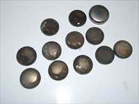
I've rebuilt several dozen of these heads and have seen this twice now, on this style engine. Coolant in the oil makes a black milk shake. The head is removed because the tech suspects (but doesn't test for) a bad head gasket. The problem wasn't with the HG, but rusty freeze plugs.
These heads have 11 of these under the valve cover, toward the exhaust side of the VC. I was able to poke a ball point pen through one of these, and another was close to rusting through. The big plug in the picture came out of the front of the head, and looks brand new.
My theory is that the coolant level drops a little, and air is introduced to the system, accelerating the process. These are not stainless like what's used in Isuzu/GM or Ford PS engines. Freeze plugs
Swapping Key Blades from Old Key Fobs
Technical Tips Forum
Robert from Florida
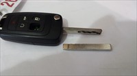
These 2 tips apply to the square "switchblade" style laser-cut key fobs used on newer GM cars and trucks. Mostly Global A vehicles like the Terrain, LaCrosse, and Regal.
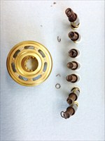
A customer comes in and wants to buy a new key fob, his old one is damaged. At first we were special ordering them, and turnaround was a week or two. These came with the key already cut, so they just had to be programmed to the car. Now we stock them, with a blank key blade, as shown here.
uncut key blade
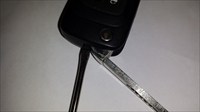
I'm told the key machine to cut these keys is $10K or more, only one dealer locally has one. We were sending porters to this dealer and paying to have the keys cut. Then someone realized the key blades are removeable, they are held in with a small roll pin.
drive out roll pin to change key blades
So you can simply swap the old key blade to the new fob by carefully driving out the roll pin using a small pin punch.
Second tip: These vehicles use a high-security immobilizer system, key fob is an important part of the system. If you read SI, to add a new key fob, you'll need to have access to TIS2web and go through a 30-45 minute immobilizer process of learning a new key fob to the vehicle. We discovered that the old transponder method of starting the car with a working key, turning it off and immediately starting it with a new unlearned key *works*. Big timesaver. So the tip is, don't install the roll pin right away. Insert the old key fob with cut key blade *loose* in the fob. Start the car, turn it off, pull the fob only, insert new fob onto old cut key and start the car. Fob is learned, now insert the roll pin to hold the old key to new fob.
| |