|
As the web has evolved over the past 19 years, so has iATN. We are working hard on several projects that will help to further strengthen the network, while staying true to our mission: "To promote the continued growth, success and image of the professional automotive technician by providing a forum for the exchange of knowledge and the promotion of education, professionalism, and integrity."
We are looking forward to the launch of these new resources in the coming months, and if you would like to be the first to hear about them, please stay tuned to the iATN Development forum, or subscribe to our "latest news" feed.
Back in March of this year we attended the ASA Midwest Vision Hi-Tech Training & Expo event where we did something new this year. We helped produce, record and live broadcast the Educator Think Tank Panel Discussion on Thursday, March 7th. Those interested can watch that panel discussion video. We also would like to thank the many members that came by the iATN booth, and appeared on camera for a new video of member testimonials. Please check it out!
As we look back over the previous quarter, we have several interesting articles in this edition of the iATN Review. Within the technical department, we have member contributions such as: Nissan NERS re-flash issue; the importance of following Chrysler WIM/SKIM module instructions which override traditional SI; a few electrical troubleshooting articles covering parasitic load analysis; short circuit analysis and starter motor diagnosis. We also have a couple fluid leak articles covering the BMW N52 and a Ford Escape trans-axle. And finally, a couple of really good shop management articles covering how to find A-level technicians, and a new twist on shop meetings. Many of these posts also lead to some very interesting discussions that you can click through to read and participate in.
We hope you enjoy this edition, and please feel free to share a copy with a colleague.
Regards,

Scott Brown
iATN President

Nissan NERS Flash Failure
Technical Discussion Forum
Matt from Minnesota
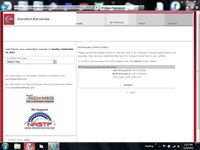
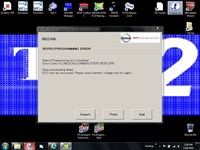
This 2011 Altima came from one of my other stores for a PCM re-flash due to a P0101. I checked the cal id and matched it to the TSB. I log into Nissan site and purchase file. 2011 cal id from nissan I set up my battery maintainer and turn odd all acc's, charging @ 13.2 volts. NERS software checks for current drivers on the Cardaq-plus, ok cardaq plus info . NERS Start Screen Hit the start button and about 50% through the flash this pops up. Flash Error I try and reboot my computer and check all connections and try again, but now I get an error saying the part number is not correct. flash failure On to email support from Nissan, after many many emails they sent a new CSV file and ask me to try it, it fails as well. My computer IT guy that just happens to work next door, came over and had a look and said maybe we change the part number that the NERS is looking for. location of CSV file here is the file opened up in 'NotePad" CSV file open in note pad. CSV file open in note pad
We changed the ending part number of ZX56A to 12345 so the NERS program could see the number that it is looking for to start programming. part number changed
I restarted programming making sure to disconnect the cooling fans as well, they were the only load on while programming the first time, Good re-flash Here is the screen shot of the before and after ECU part numbers. complete programming
The flash went just fine and the car runs great and no more false P0101 codes!
Parasitic Draw on 07 VW Jetta
Technical Discussion Forum
Mark from Ontario
Here is an interesting story about a parasitic draw on a 2007 VW Jetta.
The customer complaint was about a dead battery if the vehicle sat for more than two days. The vehicle already had a new battery in it when it got here.
We hooked up our low amp probe to the battery cable and verified an unusual parasitic draw that surged up and down between 150 mA and 900 mA.
This draw occurred with the doors,trunk and hood closed and the vehicle locked with the key out of the car. The draw went on continuously, cycling up and down until the battery depleted.
We noticed that when the driver's door was opened, the interior lights did not come on, which they did when any other door was opened. We pinpointed a defective microswitch in the driver's door latch assembly and thought this might cause a parasitic draw.
A new driver's door latch assembly (which contains the microswitch) was installed. Now the interior lights worked properly when the driver's door was opened. The parasitic draw, however, was unchanged.
After a lot of troubleshooting we discovered that disconnecting the driver's door module (integral with the window lift motor) would stop the parasitic draw.
A new driver's door module was ordered, by VIN from the local VW dealer. The new module arrived in a ripped up box with extra shipping labels on it. We installed it anyway and coded it with using Vag-Com with the same coding as the original DDM (Driver's Door Module).
Now the fun starts, since the new module would not allow any of the power windows on the car to work and it also set a trouble code, 01811 for supply voltage low.
Looking closely at the part # on the original DDM showed it to be 1K0-959-701P. The new part # was 1K0-959-701L
We called the VW dealer parts dept. and asked them to verify if this was the correct part. Yes, they assured us, it is the correct part number, only superceded, but maybe its defective.
Another DDM was ordered and arrived two days later. This one was also in a previously opened box with extra shipping labels on it. The part # was identical to the one they had just sent and it did the same as the previous module, which is set code 01811 and not work anything. There was no parasitic draw with the new module, but its hard to call something fixed when no door functions are working.
Now we noticed that the pin arrangement (and there are many pins) on the new module was different than on the original...
(Click here to read the rest of the article, including the 15+ responses received)
Finding A-level Technicians
Shop Management Forum
Nathan from Pennsylvania
Sorry folks, this may be another of those dangerous posts where I throw out what's been rattling around in my head. I was looking at the classified forum today and seeing everybody's "A-level tech wanted" "ASE Cert. tech wanted" "must be able to do all repairs" and even an ad for a service writer who can do repairs, or a service writer who knows HTML programming. These ads are from all over the country. So, I came to a couple of conclusions.
1. Lack of A-Level or Master techs is not a local problem, it's industry wide.
2. Most businesses don't seem to know what they really want so they look for a guy who can do everything
Now, it seems to me that if we just keep posting the same ads all over the place with the same "we're a busy shop, pay depends on experience" it's probably not going to get any better results than what we have gotten in the past. I responded to roughly the same ads when I was turning wrenches 15 years ago.
Is it even realistic to find somebody who can be everything to everybody in an independent all makes/all models environment? I'm sure there are some out there, but they are few and far between.
Maybe, before we go off looking for that one guy who can be our go to guy and save us from ourselves, we should take an honest look at what our business is and what do we need.
Step one - honestly evaluate where you are in the market - are you at the upper end competing with dealerships and specialty shops? are you at the bottom competing with craig's list? or are you somewhere in between. Where you are is going to determine what type of cars and customers you will be dealing with.
Step two - honestly evaluate what you need. Do you need a guy to do 40 hours of VW driveability work a week? Do you need a guy who can primarily do brake jobs with an occasional check engine light?
Step three - Can you pay competitively? If you can't, don't make promises to people you can't keep.
Step four - Think about what your vision for the company is and what your future plans are. Don't hire for what is in the parking lot today, hire for what you want to be in the parking lot tomorrow. For example, after you evaluated your market position and needs, you've decided that you want to take the car in the direction of a VW specialty shop. You are no longer looking for an all makes/all models/do everything A-Tech, you are now looking for a VW tech who can work on some other things during the transition. Advertise accordingly. Maybe you've decided that you just can't afford that super tech and it makes more sense for you to focus on the jobs that you can do and let somebody else do the other jobs.
Maybe what you really need is to re-evaluate the way that you are doing business in general...
(Click here to read the rest of the article, including the 100+ responses received)
Open Shop Meeting
Shop Management Forum
Norm from Washington
This past Friday we had a shop meeting with our entire crew in attendance. We have held shop meetings from time to time in the past but this one was different & that is why I wanted to share it here.
We relocated our shop about 14 months ago. The 6 months or so prior to the move & the 10-12 months after were quite hectic on all fronts and it was wearing on everyone. About 2 months ago I began to see it taking its' toll and told the crew we were going to get through the holidays then hold an all day "re-boot" session the first Friday of the first full week of January. I don't think all them believed we'd do it but it got us through the holidays.
Monday of this past week comes along & I gave each of the employees a letter explaining the intent of the upcoming meeting: There will be no set agenda, I have no set list of topics to discuss, everyone is asked to bring in a list of concerns or issues they would like to address and no one can make a personal attack on anyone else. If you have a concern come prepared with possible solutions to correct it and be prepared to discuss any and all topics openly. I let them know that we would be discussing company financials at the beginning of the meeting. The only prepared item I took into the meeting was a 30 minute discussion on profit & loss.
We held the meeting off-site at a rented meeting room so there would be no possibility of interruption. We had donuts, pastries, coffee, juice, fruit, bottled water, etc. available for all as everyone arrived. Everyone was told to enjoy the refreshments at will throughout the morning, to get up & stretch as needed & to remember we were there to work together, so make the most of it.
The meeting opened by me sharing with the crew financials I had never shared before, all of which were totals for the previous year: Total sales in dollars, gross profit % combined, GP% labor, GP% parts, RO averages, net profit after all expenses including my salary, etc, etc, etc. We discussed how an insurance deductible for an accident affects the bottom line & how long it takes to return that money to the bottom line so it once again becomes useful as cash flow...
(Click here to read the rest of the article, including the 30+ responses received)
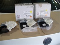
Chrysler WIM/SKIM Module (read in-box instructions or pay!)
Technical Tips Forum
Gery from Florida
Got called out today for WIM module programming. Lucky for me the parts guy gave me a heads-up to read inbox instructions. I've done so many that I usually discard any papers that come in the box.
Apparently the new WIM comes prepackaged with two keys. These two keys come preprogrammed to WIM module. If you follow "normal" WiTech instructions for WIM module replacement, you will render those keys useless and have to purchase two new keys.
Pretty much you have to write the secret key to WIM, exit, and then perform PCM replaced. If not, the secret key will not match the preprogrammed keys and...
Backfire Through Intake with No Start
Technical Tips Forum
Anthony from New York
I recently got in a 1999 Jeep Grand Cherokee Laredo 4.0L from another shop (actually a Jeep dealer here on Long Island). Well I wanted to throw this tip out there so no one else gets burned like how ever many shops got this before me. Apparently the ignition coil for a 99 is a 1 year coil and the pins are reversed in the connector on a 99 pin 1 is ignition driver #1 pin 2 is IGN drive #2 pin 3 is the ASD power and pin 4 is the #1 ignition driver.
Well in the 2000-2004 coil, (which is the only available coil now) the wires are reversed. Pin 1 is IGN Drive 1 PIN 2 is ASD power PIN 3 is IGN Drive 2 and Pin 4 is IGN Drive 3. Well long story short, you must De-pin the connector or buy a jumper harness for 80 dollars hope this save you some time fellas.
A Short Shortcut
Technical Tips Forum
Robert from New York
This week I had a car that was blowing 6 fuses. One of them instantly and the others would blow randomly. I had suspected a pinched harness somewhere. I decided to follow the circuit that blew the fuse instantly.
That would be the 40 amp power window fuse. It was a dedicated fuse for the 4 window motors and switches. The harness leaves the under dash fuse box on the left side and somehow goes to all 4 doors.
I installed my 30 amp fuse saver breaker into the receptacle for the window fuse. Now this circuit goes all through the car. In the past I would have cut wires if I could not disconnect a connector to find the general zone of the short.
This time I put my amp probe around the harness in the rh kick panel to see if the short was in the passenger side doors. Resetting the breaker and keeping an eye on the meter no current flow was observed. When I put the amp probe around the power window wire in the left kick panel and reset the breaker a brief 38 amp draw was observed before the breaker popped.
Now I know the short is between the under dash fuse block and the lf and or door. Putting the probe around both wires in the door breakout harness showed no current flow. Ok the short is in the harness between the fuse block and door breakouts. Followed the harness and found it went under the carpet on the drivers floor. Seeing as this would be the area that would get the most use I pulled up the carpet on the drivers floor.
Bingo there it is! The window wire had corroded which caused it to create heat and melt the harness causing all the other fuses to blow too.
So what I learned was instead of disconnecting harness to zone out a short , if you use an amp probe to see if there is current in that particular part of the harness you can narrow down the location of the short.
Starter Motor Failure Revisited
Technical Discussion Forum
Albin from Washington
In reply to this thread I will discuss a quick and very accurate way to test not only the starter, but the complete starting and charging system by using a lab scope, a high amp current probe and a voltage test lead.
For this test, hook the scope voltage lead to the positive and negative lead of the battery, hook the current probe around the ground wire to the battery. If there is more than one ground lead, hook your current probe around all the ground wires. You want your scope to measure all the current going in and out of the battery.
This quick and simple test will tell you about the integrity of the cables carrying the current to and from the battery, the condition of the starter solenoid contacts, the starter armature, relative compression of the engine, condition of the battery and the condition of the charging system, all with only two scope hook ups, and less than 5 minutes stop to finish of the test.
If you are using a Pico scope, put 5 minutes of time on the screen, if you are using a Snap On scope (Modis, Verus, VP) put abut 2 seconds of time on the screen. Set the voltage trace to 20 volts, and the current trace so it will capture 600 amps (if you are using a 600 amp probe). Set a trigger so the trace will be started when the starter is turned on. You should see a scope trace something like this. sulfated battery starting and charging system test Starting at the left side of the traces, I can see the starter solenoid contacts closed nice and clean, the starter got the engine running in short order, then the generator started charging the battery...
(Click here to read the rest of the article, including the 20+ responses received)
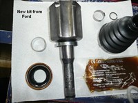
2011 Ford Escape Left Inner Transaxle Seal Leaking
Technical Tips Forum
Kevin from Manitoba
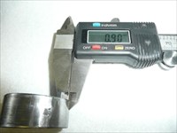
I have been seeing a few of these vehicles lately with the exact same problem where the left Inner transaxle seal is leaking. The fix is NOT just replacing the left inner transaxle seal. If you do decide to just replace the seal there is a very good possibility it will be back the next day leaking again.(grins) The problem is that the inner transaxle bushing wears out and also causes wear to the inner CV joint which compromises the seal. Here is a picture of the bushing that wears out.
2011 Ford Escape Limited, Transmission Photo
Ford indeed has a TSB on this exact situation.(TSB# 12-11-6)
It applies to the
2010-2012 Fusion
2009-2012 Escape
2010-2011 Milan
2009-2011 Mariner
The post is meant to give anyone that has not seen this problem a heads up on the repair before just selling a left inner transaxle seal thinking it will correct the leak. I have uploaded some pictures to show some details of the problems and the repair...
(Click here to read the rest of the article, including the 25+ responses received)
BMW N52 Engine Oil Leaks
Technical Tips Forum
James from Rhode Island
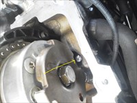
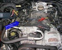
I arrived for work on Monday morning to find this 2006 325i waiting for me. Over the weekend our apprentice technician had diagnosed an oil leak to be the oil pan and oil filter housing gaskets. The oil pan gasket leak was obvious and the filter housing was too, except the front of the engine had a little more oil than you'd expect from just the oil filter housing leaking. N52 oil filter housing leak N52 timing cover leak
I figured I'd do the obvious first then wash the engine down and recheck for leaks. I had to support the engine so the subframe could be lowered to facilitate oil pan removal. 2006 BMW 325i, Engine/Propulsion Photo a little trick using the tow hook I picked up from an instructor at a BMW class in Ft Lauderdale over the weekend engine support brace to tow hook. Once I had the oil pan down I noticed something in the oil pick up: 2006 BMW 325i, Engine/Propulsion Photo there was also a bolt head in the bottom of the oil pan. Two broken timing cover bolts and one external head bolt near the oil filter housing had been mentioned in the class as being notorious for breaking and causing oil leaks that the oil filter housing gasket was being blamed for. Talk about relevant 24 hours hadn't even passed since the class.
I had our service advisor contact the customer and explain about the broken bolts the leaks and the possibility for bad things to happen in the area of the timing chain. The customer approved the removal of the valve cover to verify the timing cover bolts were broken and then to remove and replace them.
Be advised if your going to work on these all the bolts are aluminum and must be replaced when released and you'll also need a good torque wrench that can measure angle at low torque and tight spaces. The broken aluminum bolts will usually spin right out with a sharp pic although not the case with the timing cover bolts.
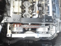
Time for valve cover removal(the valve cover is probably the most common leak on these engines and usually will have a broken bolt or two), after removing the cabin filter cowling, cross brace and plastic cover you'll need to remove the valvetronic motor: valvetronic motor release there's a 4mm hex at the back of the motor for unwinding from the eccentric shaft. Do not attempt to unbolt and pull the motor out! Remove the single valvetronic motor brace bolt to valve cover first, then loosen the two bolts at the motor flange just enough that the motor is starting to pop out then turn the 4mm hex clockwise to draw the motor towards the valve cover and remove the bolts then turn the 4mm hex counterclockwise to draw the motor out. To reinstall the valvetronic motor turn the 4mm hex clockwise so the motor pulls in flush to valve cover.
Another thing you should pay attention to when replacing a valve cover gasket is the eccentric shaft position sensor. It's the connector that goes through the front of the valve cover. If there's oil in the connector you need to replace the sensor it can cause strange driveability errors and catastrophic failures if ignored too long. No special tools are needed to replace it as the cam timing is not disturbed.
Valve cover removed and broken timing cover bolts confirmed: broken bolt I tried to spin the broken bolt out with a pic but it really didn't help. I could've tried a long left hand drill bit if I had one but I didn't. What I did have was a 16" long snap on slotted screwdriver with a 5/16" tip that I pounded an impression of a slot into that broken aluminum bolt: broken bolt timing cover to cylinder head I was then able to spin the bolt out easily and came to the next block in the road. The camshaft sensor reluctors were in the way of getting the bolts in or out.
I had to remove the camshaft reluctors...
(Click here to read the rest of the article, including the 20+ responses received)
Sync for Relative Compression Testing
Technical Tips Forum
Harvey from British Columbia
For those that don't know what relative compression testing is, it is where we use a labscope and an inductive current probe to measure the current it takes to spin a starter. Each compression stroke will cause the current requirements of the starter to increase during the compression stroke versus the other strokes. The higher the compression, the more current it needs. The lower the compression, the less amperage it needs for the compression stroke.
We can use this to "see" if we have a cylinder or cylinders that are low in compression. Because we don't measure the actual pressure, we typically compare one cylinder to the next. Hence the term "relative".
For those that perform relative compression testing, we know how quick this test is to confirm if there are any mechanical issues or not. If I have a misfire and perform this test and find low compression, I'm almost done my diagnosis. It can be a good quick first step. And it should be the first step before any transducer testing.
We also like to have some sort of "sync" or marker to indicate which pulse is which cylinder. Typically, we like to use the coil firing as the "sync" as that indicates, not only which cylinder is on it's compression stroke, but we can also judge approximately where TDC is.
In order to prevent the vehicle from starting, and still have spark to "sync" off of, we have to disable the fuel system. Different vehicles have different methods to disable fuel. Some we just fully depress the accelerator pedal and achieve a "clear flood" mode. That's the simplest, if it works. Some have fuel pump relays that we can remove. Others need slightly more work to disable fuel, I've disconnected all the fuel injectors in some occasions...
(Click here to read the rest of the article, including the 25+ responses received)
Relative Compression via Voltage
Technical Theory Forum
Samuel from Colorado
In the tool equipment forum there was some discussion about BOB uses and it was mentioned about using it for relative compression testing.
It is possible to do a relative compression test via just battery voltage. Pico diagnostics has had this setup for a while. The earlier version could also display what was connected on channel B. So, I decided to see how much of a variance there was between the battery voltage and BOB voltage.
First up is my connections:
2000 Dodge Dakota, BATT/Charging/Starting Photo
2000 Dodge Dakota, ECM/Inputs/Outputs Photo
My first test was using the Pico diagnostic relative compression test. I use this a fair amount as a go, no go on mechanical, combined with listening to the cranking cadence.
2000 Dodge Dakota, BATT/Charging/Starting Photo
In this case PD display the second channel as AC coupled and the peaks are relatively even.
OK, next up is connect all four channels two DC coupled, two AC coupled, the test points are the battery and the BOB pin 16. I did a vertical zoom on the DC coupled, and filtered all four channels. In this case looks like the results are very similar.
2000 Dodge Dakota, BATT/Charging/Starting Waveform
psd:
2000 Dodge Dakota, BATT/Charging/Starting Waveform
And just in case anyone is thinking I am a Pico snob, here are some Red tool (Modis) captures. As far as I know there is not a vertical zoom so I just did an AC couple and again the connection is the battery on one channel and BOB pin 16.
2000 Dodge Dakota, BATT/Charging/Starting Photo
2000 Dodge Dakota, BATT/Charging/Starting Photo
2000 Dodge Dakota, BATT/Charging/Starting Photo
The results again seem very close. I can not say it will be the same on every vehicle, but it seems like something to play with. Also worth noting is there is a relationship between the battery voltage and the current. A bad cylinder will be opposite of what a current probe would.
Anyone else try this out yet? if so, feel free to add your captures.
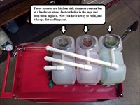
Budget Build, $149 Coolant Vacuum Fill Cart
Tool & Equipment Forum
Steven from Washington
Assuming you already have a vacuum fill tool and some adapters, you can build this general overview for around $149.00
Harbor Freight cart $40.00
2.5 gal jugs of water ($3 each) $9.00
Stuff from hardware store $100
Okay, so if you don't have a vacuum fill tool or radiator adapters, then add that cost to your build. I recommend a quality vacuum fill tool because I tried a cheap one from Astro Pneumatic and it did not work. However, the pressure test kit from Astro Pneumatic is excellent for this project. It has quick connect adapters that you can incorporate into this build and the cost is pretty low for the amount of adapters you get.
Here's the complete story as to why I built this in the first place, and some pictures and details of the project following that:
When I started this new job at European AutoHaus, I quickly learned that there wasn't a coolant refill machine. All the techs had there own vacuum fill tools, so I went ahead and bought one for myself and a couple adapters. Unfortunately, I bought them from the Snap-on truck and man was the cost starting to add up!
Another problem I discovered was that these vacuum fill tools are messy! Little coolant drips everywhere on the floor, and when you roll the hoses up and put it away coolant drips all over. No matter how much I tried to shake all the coolant out of the hoses, there was still some left over just waiting to drip all over.
I had enough! This is a ridiculous way to do this! I want my coolant machine back!
I thought about buying my own coolant machine. The cheapest one is about $750 and only does one coolant, so you would have to change out the coolant every time you had to switch to a different coolant type. Then, I found one that had three separate coolant containers, but that one was like $3,000!
Time to get creative. Here's a schematic of the basic way to build this type of thing Coolant vacuum fill schematic
(Click here to read the rest of the article, including the 35+ responses received)
| |