|
We've temporarily renamed this newsletter iATN ReSearch, to celebrate the release of our brand new search engine. If you haven't tried it yet, I encourage you to explore it here: search.iatn.net. The new search engine is smarter, faster, and will make your research work more efficient, because we now search across the entire iATN Knowledge Base.
If you're researching an issue about a specific vehicle, use our Smart Vehicle Builder technology by typing the year, make and model, and choosing the vehicle from our auto-suggestions. For example, try typing "08 f3" (without the quotes), and we'll quickly show you the available 2008 Ford F-350 models and engine packages (notice we didn't even have to type the 4 digit year, or the make). If you have a VIN, type or paste it in, and our VIN decoder will instantly define the vehicle. Here's a short video which demonstrates the Smart Vehicle Builder.
Once you have based your search on a vehicle, try typing a common automotive term, such as "no start" (without the quotes), and you'll see the power of SuperCharged Search, courtesy of our sister company, Identifix. This allows us to find results based on similar terms, such as "won't start," "will not run," etc.
We will be continuously improving and refining the way this new search engine works in the coming days, weeks and months. If you have any questions or feedback about it, use the "Feedback" link on the lower/right side of the search engine. Keep an eye on our videos page for more search tips and tutorials.
In this edition, you're bound to find some interesting articles written by iATN members during the second quarter of 2013. There's something for just about everyone, including articles about: Media Oriented Systems Transport (MOST) ring breaks in networks found on GM vehicles, scan-tool bi-directional capabilities, FORD PCM tear-tags, a vacuum waveform analogy, Chrysler timing belt replacement tech tips, Ford modular engine spark plug issues, Chevrolet Cruze timing tools tutorial, and an article that took advantage of our recently overhauled file upload system, which now allows members to upload raw data files from many of the tools out there today, including: Pico, Ford IDS, GM Tech2 & MDI, most Snap-on models and many others. For more information about the new file uploader and data file support, please see this forum post.
We hope you enjoy the new search engine, and this edition of iATN ReSearch! ;-)
Regards,

Scott Brown
iATN President

MOST Ring Breaks in NGI Systems
Technical Tips Forum
James from Florida
This post will most likely be of interest to GM techs only at this time as this technology has not filtered down to the aftermarket yet.
Finding MOST ring breaks can be done without too much trouble if you have a good idea how the system operates. The MOST network is a chain type unidirectional network. The radio is used as the MOST master module in most cases. It is also used as the MOST to low speed GMLAN gateway module and is usually assigned MOST module 1 position. During a ring break, communications will cease on the nework and only node ID's will be reported.
If a MOST ring break occurs, the radio will report U0028. To determine the site of the ring break, check the MOST network parameters. The LAST WORKING MODE ID will always be present, but the SURROGATE MOST MASTER NODE UPSTREAM POSITION will only be present while the ring break is active. When the ring break occurs, the module in the ring after the break will report itself as the surrogate MOST master module. This is important as the unidirectionality of the network will point out the break area as between the surrogate MOST module and the MOST master module.
By looking at the LAST WORKING MOST MODE ID numbers reported and the position of the MOST module that declared itself as the SURROGATE MOST MASTER NODE, the ring break position can be estimated from the driver's seat before intrusive testing.
Ford Tear Tags, Rebuilt PCMs, NASTF 519
Technical Tips Forum
Michael from New Jersey
My position as "NAPA Flash" exposes me to all levels of technicians, parts and circumstances regarding vehicle modules and installations. I program new, rebuilt and even used modules for our local customer base. Some ECMs are only available through the oem dealer network; which lead to my filing an NASTF information request.
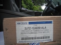
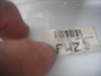
I was called to do a pmi (programmable module installation) on a Ford vehicle. The replacement module was a rebuilt unit from Ford. The instructions with the unit were very specific; use the tear tag to correctly program the replacement unit. Ford replacement module instructions The pcm had been replaced with another unit, all tags had been removed. The tear tag was barely legible; but I could read some of the letters. I verified the tear tag by inspecting 2 other vehicles in the customers fleet.
What about next time, when there were no labels, tag or fleet vehicles to use for information? I tried to discover if there was a method to obtain tear tag codes through VIN information. I did not receive any positive answers. I then e-mailed the Motorcraft IDS help line. I was told to take the car to the local dealer. I reviewed all of my information, or lack of information and decided to file an Information Request with NASTF. Even after I quoted the instructions contained in the Ford replacement module; Ford informed NASTF that there was no way to obtain tear tag information. NASTF closed my request because no one, even Ford dealers, could obtain the needed information in an official manner.
I responded to the Ford representative that I was amazed that and authorized Ford dealers and certified Ford techs were left to their own devices to correctly program a replacement module. Further correspondence from Ford stated they would research this information gap.
While pondering my next move, I received a e-mail from Mr Kevin Brady, IDS Director, Ford Engineering operations, acknowledging the information gap and the proposed fix. Tear tag information would be included in most as built listings. Response from Ford.
Here is the result. Replacement Ford module replacement module from Ford, replacement module tear tag with different tear tag. Tear tag on cowl. Original tear tag on vehicle, hard to read, will soon fall of vehicle. Vehicle vin sticker. Vehicle getting replacement module, Ford as built request, requesting tear tag info, as built information with tear tag. As built info with tear tag.
Thanks to Ford for addressing the problem and providing a speedy resolution.
I would advise to use the tear tag method on every Ford module replacement.
Battery Registration on BMW
Snap-on Handheld Users Group
Harvey from British Columbia
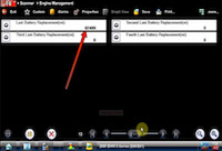
Previously in another thread, I upload a video showing how to navigate to the battery management screen of a Snap On scanner. A question was posed by a member would couldn't figure out how to tell if the battery registration worked or not. While I could have replied to that thread, I thought it was best to start a new thread so that it could easily be found should other members have the same problem.
I hope this movie explains all the steps necessary to perform a battery registration. This particular procedure was performed on an E90 vehicle.
[2006 BMW 325i, BATT/Charging/Starting Video]
Harvey.
If it Walks Like a Duck, Talks Like a Duck...
Technical Discussion Forum
Harvey from British Columbia
It must be a chicken!
Had a Intrepid towed in for a no-start. One of my techs had a look at it. He said that it sounded like it was out of time and thought he'd try this technique that he read about. The technique is scoping cam and crank and see if they are in sync.
Here is the capture he showed me of the crank and cam during cranking.
Looking at known good captures, this capture is in sync. Cranking the engine, it will kick back and backfire out of the intake periodically. Definitely sounds like its out of time although the cam/crank says otherwise.
I thought it would be prudent to take a capture of in-cylinder while we're cranking. Here is the capture of cam/crank with #1 in-cylinder. Little different result eh?
It looks like it jumped time, but jumped to a spot that the crank and cam pulses lined back up! I thought I'd share this as it was pretty neat.
For those that use Pico, here is the scope capture in .psd format.
Harvey.
Vacuum Waveform Analogy and ID Help
Technical Tips Forum
Mike from Ohio
Here is something that seems to help me in understanding a vacuum waveform. I'm not claiming to invent this and actually didn't even bother searching much to see if this same idea was posted before.
So far I really see this cranking vacuum waveform thing as very useful. I thank my buddy Brian T. for making me revisit the idea. Thanks also goes to the Brandon B at autonerdz for this awesome idea for a $3.00 BLS I have come to love. This is obviously done on a pico but if you have a sync probe for your scope and buy an FLS or make the BLS you can do this with any scope !
Most of you know the vacuum waveform is quite difficult to master. At least it is for the simple minded techs such as myself. The cylinder ID can be helped greatly with a WOT overlay but is still a little cumbersome IMO. This way is sort of crude but I think its down, dirty, and effective it can just be jotted down on a piece of paper if needed.
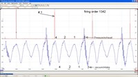
Most everyone knows about companion cylinders and how to find them right ? For those who don't its really simple take the firing order and break it in half. This one 1342 put the first two numbers 13 on top of the second set 42. So 1 and 4 are companions and 3 and 2 are companions. This means the piston is in the same place as its companion . Knowing this is huge in this simplification process. If we sync #1 to a plug wire or coil we will have this easy to follow map. 1994 Plymouth Sundance Duster, Waveform
I you look at the sync probe in red on #1 wire the first blue trace right under it is the companion cylinder #4 exhaust stroke. If you label the top humps the firing order starting there you get 4213. Since you know that the vacuum event happens right after the exhaust event the first dip in the waveform has to be #4 intake stroke. So you label the bottom 4213.
I don't know why this seems easier to me? Maybe if your struggling with the vacuum waveform this may help you out as-well. I didn't bother posting this in Autonerdz because those guys are way beyond this. This is baby step stuff for most of the guys there .Im quite intimidated there and I feel like it would be more useful here. I really like reading there just don't feel I have much to contribute. I hope nobody has any hard feelings. I am only sharing something I find really cool. If anyone has anything to add please do.
Oh yeah # 3 exhaust follower fell out as that valve is stuck slightly open.
I know this is an easy one and being a 4 cylinder makes it nice with not so many events. The principal still applies to V engines and it seems like cranking waveforms quickly rule out a (major problem) quickly. The running really didn't look much worse I just had to change the scaling a lot and even added some filter.
Chrysler 2.4 Timing Belt Alternative
Technical Tips Forum
Patrick from Virginia
The Chrysler 2.4 Timing Belts can be a real pain to line up because the right strut tower is right in the way of the marks. They also dont give you a mark on the top of the pulley. They give them to you on the sides that you have to try to run a straight edge over. It is very easy to be a tooth off in either direction. Add to this if the vehicle came to you with a broken or slipped belt it can be very difficult. As a result, I took some pics and wrote up this alternative method after I finished one of these recently. This method works very well if the timing belt is broke and none of the pulleys are in time. [2005 Dodge Stratus SXT, Engine/Propulsion Document]
Ford Spark Plug Problems
Technical Tips Forum
Matthew from Illinois
I have seen many people posting on iATN having spark plug problems on Ford modular engines. I have experienced many of these problems myself. I made a presentation for my students about the different problems with the engines, and wanted to make it available for everyone else. I would be more than happy to hear if anyone else has more tips, or finds any errors. I am trying to make this the most complete and correct Ford spark plug guide, and this is my first draft.
Thanks, and everyone have a great weekend! [Ford Spark Plugs]
Electrical Connections Again - The Inspection
HD/Fleet Forum
Andrew from Utah
Dean was kind enough to send me his wiring connection from the following post: Electrical Connections Revisited.
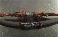
I inspected it, sourced some solder seal connectors did a regular solder joint and did some comparisons with pictures. Here are the results.
At first glance it looks like the joint Dean did looks to be ok. Looking closer shows some serious flaws in the solder joint. A good solder joint will be shiny after completion, the solder will have flowed freely through the strands of wire and filled in the gaps. The solder seal connection left a dull appearance with lumps and poor flow. Very characteristic of a cold joint where the solder was hot enough but the surface was not hot enough for adhesion and flow. [Comparison] Any tugging on the wires at all and the solder would peel off the wires. Proper joints will not do that. [Teardown]
Next I tried several temperature ranges with the solder seal connections and a propane torch to see what the results would be. Would it be possible to get a good solder joint? I used a 16 gauge wire for the benefit of better wire heating for proper adhesion. Thicker wires take more heat.
The first try resulted in a job very similar to what was listed earlier. A clean shrink and the solder ring collapsed into the wire. [Good Shrink] A job most techs would be proud of. After cutting away the heat shrink I found this [Good Shrink 2] [Good Shrink 3] While the solder did indeed melt and get squished into the wire by the shrinking heat shrink the solder did not penetrate the joint or flow well. I tried this several times with similar results each time.
Next was to use less heat. [Cold Shrink] The heat shrink did its job by shrinking down and sealing to the wire. The problem is it sealed before the solder ring collapsed leaving an air pocket. The solder did eventually melt but there was nothing to push it into the wire let alone ability of the wire to get hot enough for adhesion. [Cold Shrink 2] The result was a miserable failure.
Last I tried to get the joint hot enough for the solder to flow properly. This can be successfully done if you don't care about the seal. [Hot Shrink] Heat has to be kept on the joint after the heat shrink has shrunk and the solder ring collapsed. Otherwise the wire won't get hot enough for adhesion and flow. [Hot Shrink 2] You can see where there was good flow and it is shiny on the left side. The right side was too cold, is dull and didn't flow well. not much of a temperature difference side to side but it was enough.
I have concluded as before that the solder seal connectors are cold solder joints which hold the wires together for rigidity and nothing more. Although there are probably a lot of applications where they will work well, such as trailer lighting, I would never use them on a circuit where voltage drop is a critical issue, such as throttle actuator circuits. Definitely better than a scotch lock but there are much better options such as proper crimping and adhesive lined heat shrink tubing or solder and adhesive lined heat shrink tubing.
Chevrolet Cruze 1.4L LUV Timing Tools
Tool & Equipment Forum
Martin from British Columbia
This post will provide a little visual insight and some tool information related to various service procedures on the engine camshaft and timing system on Chevrolet Cruze 1.4L turbo RPO LUV) engines. Whether working on a Cruze LUV or a Volt LUU, the same tools are required.
Whenever various procedures are performed, from camshaft phasers, timing components, camshaft replacement etc., precision alignment of the timing components is necessary. On this particular engine family, there are more tools required than on some earlier engines, which appear to be similar.
There is no provision for "guess and by golly" techniques of "yesteryear" to be the option when servicing these and many other modern engines. During a procedure, I had my camera handy and thought it worthy to share the photos of the main tools in use as a visual aid. Some tools referenced here are not shown, but are necessary for all of the timing components to be precisely positioned.
Note that when the camshaft bolts are loosened, they must be replaced, since they are Torque To Yield (TTY). Hold the camshafts with a wrench on the hex behind the camshaft phasers while removing or torquing the bolts.
Not shown is the crankshaft fixing tool EN-952 (KM-952). It is installed at the lower front of the crankcase, to engage in an alignment hold in the crankshaft, once a plug is removed from the cylinder block. The tool should not be forced or bind in the hole when the crankshaft is correctly position. While it is not shown, this is an important step, not to be omitted. Just as important, is to remember to remove the holding tool and reinstall the plug when the procedure is complete. If you think that you might forget this step, put a Post It note on the driver's door or steering wheel as a reminder!
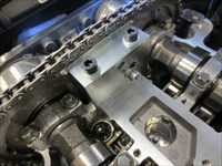
[2012 Chevrolet Cruze LT, Engine/Propulsion Photo] shows the camshafts held in correct position, similar to other engines with slots at the rear of the camshafts. It may be necessary to use a wrench on the camshafts to engage the tool fully into the slots.
Since the engine has camshaft phasers, tools are required to ensure that the phasers are correctly positioned relative to the camshafts. This is accomplished by installation of a holding tool to the intake cam phaser sprocket. [2012 Chevrolet Cruze LT, Engine/Propulsion Photo] shows the tool as installed in the front view and [2012 Chevrolet Cruze LT, Engine/Propulsion Photo] show the installation rear view.
As mentioned, the camshaft bolts which also serve as the hollow hydraulic camshaft phaser control valves, are TTY. [2012 Chevrolet Cruze LT, Engine/Propulsion Photo] shows the intake camshaft solenoid removed exposing the bolt. This bolt secures the camshaft, phaser and exciter ring together.
Hold the camshafts with a wrench whenever loosening or tightening and torquing this bolt. The tools are intended for alignment of the timing components, not holding tools for removal and torquing of tight fasteners.
Locking pins EN-955 (KM-955) are used during chain and phaser procedures to maintain chain tension, but not shown in photos here.
Since the camshaft exciter rings camshaft phasers and camshafts have no dowels or tangs to maintain alignment, once installed they rely on a consistent clamping load of the new TTY camshaft bolt, to hold them securely in alignment. Shown in [2012 Chevrolet Cruze LT, Engine/Propulsion Photo] is the exciter ring positioning tool. The tool engages in slots in the intake and exhaust camshaft exciter rings and again, the tool is not used to hold components while loosening or torquing the camshaft bolts. [2012 Chevrolet Cruze LT, Photo] shows the slot in the intake cam exciter ring.
Without going into lengthy details of the various procedures associated with the need for the tools depicted in the photos above, it is essential that the set up steps of the procedures be followed in the correct order to accurately time the involved components. The tools are available through Kent Moore and where applicable the EN (Engine) and KM # or other is shown.
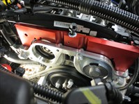
Note that the camshaft cover gasket is rubber and fits into a groove similar to many other engines. It should be replaced not re-used when the cover is removed.
The Power of Built in Scan Tool Functions
Technical Discussion Forum
Shannon from California
I had a 2005 Ford Taurus come my way requiring a drivability diagnosis. It had a dead misfire, and even taking the misfire into account it was idling very poorly. I checked Continuous Mode DTCs, the P0171 Freeze Frame, and PCM KOEO codes . There are many ways to handle this vehicle, but I'll share what I did with my IDS.
First, I checked power balance. Next, I checked relative compression. I then checked relative injector flow. I was already in the Fuel System tests, and I did have a P0171 so I thought I'd just check running fuel pressure and fuel pressure leak down really quickly. I already knew where I was going for the misfire, but before I got out of the driver seat I thought I'd just peek at some scan data.
At this point I already know I have an ignition system related misfire. Not hard to guess, certainly not hard to determine through other methods. I was able to quickly eliminate/confirm a variety of things and narrow my testing down to the most pertinent area.
I put my capacitance pickup on cylinder #3's ignition cable and checked Power and Waste secondary waveforms. The spark is not occurring in the combustion chamber. I put a spark tester set to 20kv on the end of the ignition cable, and a low amp probe around the coil common power wire. No spark at the spark tester.
100k on the odometer, original plugs, orginal ignition cables, and a defective coil. A set of plugs and cables, with a new coil and the misfire was corrected. A KAM Reset, fuel trims back to normal, misfire gone, and away goes the vehicle: fixed.
This was not a complicated failure, nor a complicated diagnosis. This vehicle certainly could have been diagnosed a number of ways utilizing a wide variety of tools and/or methods. Still, the power of the built in test functions of the Ford IDS for this vehicle made it a no risk, low effort, high comfort diagnosis.
| |