|
This edition of the iATN Review is packed with some great material posted to iATN over the last quarter. Inside you'll find a great writeup for those considering the purchase of Chrysler's wiTECH platform, an extensive pictorial covering the replacement of the HVAC MMA assembly on a 2011 Ford F-250, another nice write up with images on the replacement of the EBCM in a Chevrolet Volt, how to rebuild the EATC on an 02 F-250, Hyundai Fuel Evap diagnostic tips, Electronic throttle control diagnostic tips and to round things out, an article providing a great tip when addressing parasitic loads.
New Features Coming in Early 2013. Over the last half year, we've been hard at work on two major features for iATN that we think you're really going to enjoy.
The first is a brand new search engine that we've been focused on for many months. We are planning to start the search engine beta test imminently. If you are interested, please join the search beta test.
The second is a long overdue feature: iATN mobile apps for iPhone, iPad and Android phones. We are making great progress here, and look forward to inviting beta testers to help us test these apps over the coming months. We'll announce more as soon as we can. Be sure to follow iATN on Facebook, Twitter, Google+, LinkedIn or RSS to get the latest news as we post it.
Vision 2013 Kansas City. I'll be presenting at Vision 2013 in Kansas City (March 7 - 10), within the "Educator Think Tank" course category, on Friday (March 8) from 1:15 - 3:15. The title of my course is "Mastering iATN." In addition, iATN will be in booth 717 Friday thru Saturday (March 8 - 9). Stop by and see us! You can register for Vision here.

Scott Brown
iATN President

Chrysler wiTECH Purchase Information (New and Existing)
Tool & Equipment Forum
Dan from Virginia
I contacted DCCTools [dcctools.com], and asked what it would cost to purchase the latest Chrysler scan tool. An account was created for me and, with the user ID and PW email, I received this: [wiTECH Special Instructions Email] Pay attention to the Special Instructions.
I was told the least expensive route is to purchase the wiTECH LITE Kit for $3650 plus shipping. This does not include the subscription to TechAuthority [techauthority.com] ($35 3-day/$250 30-day/$1800 1-year/and various multi-user plans) should you wish to program modules.
This LITE Kit includes wiTECH Application, wiTECH VCI Pod Kit, wiTECH Access Point, and emailed setup instructions (may require some IT assistance) that are to be performed prior to delivery of the kit. It also includes email technical support.
The wiTECH System, $5842 plus shipping, includes wiTECH Application, wiTECH Access Gateway, and wiTECH VCI Pod Kit, installation/setup and technical support via phone.
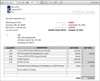
Next I asked how a person should proceed if they have a wiTECH VCI Pod in their possession (let's say the Pod was purchased from a Chrysler dealership) and I was advised to purchase the wiTECH LITE Kit for $3650 (plus shipping) and a VCI Pod Support Bundle (good for 1 year) at $285. Total cost $3960 (plus programming subscription as needed). [wiTECH Price Quote] To accomplish this, they need to know the end user's account number and the serial number of the VCI Pod.
Next up, StarMOBILE. Same deal, purchase the wiTECH LITE Kit for $3650 (plus shipping) and a StarMOBILE Support Bundle (good for 1 year) at $320. Total cost $3995 (plus programming subscription as needed).
I asked about renewals and here is the response I received:
Q. What is the cost to continue/renew after the first year of wiTECH System use?
A. $1300.00 (1 Year wiTECH System Maintenance Bundle)
Q. What is the cost to continue/renew after the first year of wiTECH System use on an account that has added a previously purchased wiTECH VCI Pod to the account at the initial purchase of the system?
A. $1300.00 (1 year wiTECH System Maintenance Bundle) and $285.00 (VCI Pod Support Bundle)
Q. What is the cost to continue/renew after the first year of wiTECH System use on an account that has added a previously purchased StarMOBILE to the account at the initial purchase of the system?
A. $1300.00 (1 Year wiTECH System Maintenance Bundle) and $320.00 (StarMOBILE Support Bundle)
Q. What is the cost to continue/renew after the first year of wiTECH LITE System use?
A. Not in the shop portal yet, It is subject to change - $500.00
Q. What is the cost to continue/renew after the first year of wiTECH LITE System use on an account that has added a previously purchased wiTECH VCI Pod to the account at the initial purchase of the system?
A. $500.00 (LITE Support) and $285.00 (VCI Pod Support Bundle)
Q. What is the cost to continue/renew after the first year of wiTECH LITE System use on an account that has added a previously purchased StarMOBILE to the account at the initial purchase of the system?
A. $500.00 (LITE Support) and $320.00 (StarMOBILE Support Bundle)
Here are some of the screen shots from my visit to my wiTECH account page.
System Pricing [wiTECH System Pricing Page 1/2] [wiTECH System Pricing Page 2/2]
VCI Pod Accessories [wiTECH VCI Pod Accessories Pricing 1/2] [wiTECH VCI Pod Accessories Pricing Page 2/2]
StarMOBILE Accessories [StarMOBILE Accessories Pricing Page 1/3] [StarMOBILE Accessories Pricing Page 2/3] [StarMOBILE Accessories Pricing Page 3/3]
wiTECH Specialty Items [wiTECH Support Licenses]
wiTECH Support Bundles [wiTECH Specialty Items Page]
A very helpful Knowledge Base is available here [kb.dcctools.com].
So if you have a Pod that you wish to link to an account, the least expensive way in is to purchase a wiTECH LITE kit ($3650 + shipping) and then attach the first Pod to the account (DCCTools will verify the serial number and charge $285 for the support bundle). Total initial cost will be approximately $3960. Then the annual cost to remain in the game will be $500 for the wiTECH LITE kit plus $285 for the extra Pod (Total of $785/year). If you are adding a StarMOBILE to a wiTECH LITE account, the initial cost of the wiTECH LITE kit and addition of the StarMOBILE support bundle is approximately $3995. Annual renewal cost will be $820/year.
If you recently purchased or are going to purchase a wiTECH System or wiTECH LITE Kit and your experience is different than what I describe, would you please reply to this post describing your experience?
Thank you!
2011 F-250 - Multiplex Mode Actuator Assembly w/ Cable
HVAC Forum
Glenn from Louisiana
2011 F-250 SD P/U - Multiplex Mode Actuator Assembly w Cable
Informational systems do not always supply us with a picture perfect course of action or a picture perfect ending. For instance: newer informational systems commonly lack real-life photos, pictures that depict the actual information, illustrations that do not mislead, and so-forth; which relates to an actual loss of a thousand words or more for each omission. Further, we pay for such lacking and substandard information.
To better understand the above statements, review the following provided herein regarding a 2011 Ford F-250 Super Duty Pickup. After you review the following, access your informational system and see how the following relates, or not, for the information you are paying for.
Complaint: lower than normal air flow (which by itself can be misunderstood by many technicians with newer vehicles concerning multiplex inclusions and technologies).
Verification: modes unable to complete, weaker than normal panel register air flow, weaker than normal floor duct outlet air flow, simultaneous panel register airflow and floor duct outlet airflow, and no defrost duct outlet air flow.
Diagnostics: no DTCs (in this case), able to send commands to MMAA, signals received at MMAA, limited movements of MMAA, and unable to achieve MMAA actuals (targets).
Plan of action: remove MMAA to verify all associated modes, and mode components, for proper function/movement.
Course of action: simple . . . right? Well, unless there is a way that doesn't require cutting or the hot-wrench, the next course of action is a bit entailed. To keep everyone awake, the basics were skipped . . . and, fast-forwarded to: disassembled and photos.
(Click here to read the rest of the article, including all 27 accompanying photos!)
2013 Chevrolet Volt EBCM Replacement
Technical Discussion Forum
James from Florida
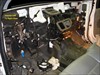
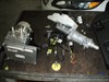
I had the enviable opportunity of replacing an EBCM in a 2013 Volt. They are bolted to the BPMV in such a way that the BPMV and it's mounting bracket must be removed first in order to replace the EBCM.
Here's a view before disassemble. Can you see the EBCM?
[2012 Chevrolet Volt, ABS/Inputs/Outputs Photo]
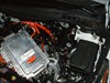
Let's get the PIM and other components out of the way first.
[2012 Chevrolet Volt, ABS/Inputs/Outputs Photo]
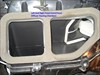
There it is. You can see it but you can't remove it without pulling the master cylinder and all the lines and hoses first.
[2012 Chevrolet Volt, ABS/Inputs/Outputs Photo]
There it is now on the bench, ready for R & R.
[2012 Chevrolet Volt, ABS/Inputs/Outputs Photo]
Looks like fun, doesn't it. The best part is yet to come. Don't ask about bleeding the system or relearning components. It makes you feel that the R & R was really the easy part...
2002 Ford F150 EATC Control Head
Technical Tips Forum
Danny from California
The customer complaint was at times air from the panel vents would switch up to the defroster vents. This would often times happen when accelerating on an on ramp. Usually one would find a degraded vacuum hose to the HVAC system by the battery that would usually cause this problem.
When I got the vehicle, the air was constantly being diverted to the defroster vents. I removed the EATC control unit, and found that the vacuum source was present, and that all of the vacuum motors operated properly when tested with a vacuum pump. That pretty much left the EATC as the problem.
The consumer balked at the cost of the EATC from Ford $365, and asked if there was a rebuilt unit available. Searching online I found this thread [f150online.com].
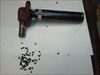
It seemed straightforward enough, so I followed the procedure, and I took a picture of the disassembled EATC control head.
[2002 Ford F-150 XL, Photo]
The unit works flawlessly. When I started the truck this morning the air was blowing through the panel vents from the get go. All 4 "O" Rings should be replaced. The 4 solenoids share a common vacuum source, and I would think having only one leaking would degrade the performance of the control head.
ABS, Service 4WD, Loss of Blower Motor
Technical Tips Forum
Dale from North Dakota
I've run into 3 of these with identical problems recently so I'm guessing that there's lots more of these out there. Vehicle came in with "Service 4wd" message, ABS and Brake warning lamps on, and no blower motor operation. All problems occurred at the same time. Service code for ABS was U1041: Loss of communication with Brake system controller. Transfer case code was C0379: Front axle circuit malfunction.
When checking fuses it was found that the 4WD fuse, 30 amp blower fuse, and 10 amp Brake fuse didn't have any power at them. A quick check of power distribution showed that they were all powered through the ignition switch via pin G and a large orange wire which goes to a 6 pin connector at the back of the IP fuse panel.
When testing this circuit it was found that the orange wire was discolored at the 6 pin connector and was no longer feeding power to the fuse panel. Removing the female terminal from the 6 way connector revealed that there wasn't a good connection between the female end of the orange wire and the male pin at the fuse panel. Cleaning the male pin and re-soldering and tightening up the female connector has fixed all three of these.
I think the problem is two-fold. First, it's a lot of power to run through the small spade connector and second, the way the harness runs and is fastened between the steering column to the fuse panel can cause the orange wire to be stretched and strain the 6-pin connector when the column is tilted at just the right angle. Improving the connection so it flows current properly and removing the clip that holds the harness at the stretched out position is the fix. The harness can't go anywhere or get into anything with the push-in clip removed so there's not a concern there.
Hope this helps someone else down the road!
Hyundai Evap
Technical Tips Forum
Tom from Illinois
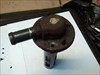
When testing EVAP systems for problems don't forget about the ORVR. The complaint on this Hyundai is difficult to fill fuel, the pump keeps shutting off. Someone has already replaced the canister and the vent valve.
Here is what I found. Hyundai calls it the Fill vent valve (ORVR) and it is mounted on top of the fuel tank. [2002 Hyundai XG350 L, ECM/Inputs/Outputs Photo] [2002 Hyundai XG350 L, ECM/Inputs/Outputs Waveform]
Look at all the charcoal that came out. The valve was stuck closed. [2002 Hyundai XG350 L, ECM/Inputs/Outputs Photo]
MAF Sensor / Engine Breathing
Technical Theory Forum
Shannon from California
While I am working on a 2007 Mini Cooper S with a Turbo (N14), this post is more about general theory. This Mini has a pretty consistently reoccurring P115C / 2B5C AIRFLOW PLAUSIBILITY code. It has no other codes. According to my information this code indicates actual air flow is lower than expected. The vehicle has an intermittently varying harmonic surge at idle, but no other drivability symptoms.
The freeze frame is always after it has been running quite a while (1500+ seconds) and always at about 800rpm with vehicle speed being 3-7mph. The fuel trims in the freeze frame rarely are more than +/- 1. I would love to have a PID that indicates air flow error, or something similar, but I don't seem to. In all my test drives the OBDII fuel trims are well balanced. I'm not familiar enough the Mini factory side of the data to make much use of the fuel trim information available to me with my aftermarket tools. Lastly, this vehicle has a brand new factory MAF on it.
I suppose a quick question is: Is OBDII fuel trim reliable/accurate for this vehicle?
My main question about theory relates to this MAF plausibility code and engine breathing on a single bank system.
In any engine with a throttle blade I would imagine that a majority of the time the throttle blade is the greatest restriction. At some point of throttle opening I would also imagine that valve ports may become the greatest restriction.
If there is a leak between the MAF and the back of an intake valve then there should be evidence of this in the fuel trims. If there was enough of this issue I would suspect the engine management system would set a fuel adaption code.
Low MAF reading versus expected could also be caused by an intake or an exhaust restriction. Anything that reduces the air flow of the engine, itself. In both of those cases there shouldn't be a fuel trim problem as the MAF is reading what is actually getting into the engine. Having a turbocharger or supercharger shouldn't make a difference, even if there was a problem with it, because it would be behind the MAF, right? Would an issue with the turbo/supercharger generating boost cause lower than expected MAF readings?
A backpressure test, of some sort, should reveal a restricted exhaust. I would also think there may be a power/drivability issue evident.
A restricted intake would also lower actual air flow. A restricted intake from carbon, for example, on many of these GDI engines. In the event of a restricted intake on a direct injection engine there shouldn't be a fuel trim/adaption issue. Wouldn't that intake have to be pretty severely restricted to be the greatest restriction, in most cases? Especially at idle/near idle RPMs? Wouldn't an intake restriction have a more severe effect with increased engine RPM? Also, I would think an intake that restricted would cause misfires.
This vehicle does have a previously identified moderately carbon'd intake manifold.
Lastly, any valve timing and/or variable valve timing issue could change the breathing characteristics enough to set a plausibility code. I would think these conditions would also set additional codes. I'm not entirely sure if there would be a fuel trim issue present, but if the MAF is reading the actual air flow, I don't see why the fuel trims would be skewed.
I am trying to diagnose this Mini, that is true. I'm also making sure my MAF and air flow theory is sound and correct. Every so often we run across a vehicle that challenges the way we think about things, and what we think we know. This vehicle is like that for me, and that's why I posted this in TTF instead of TDF.
Getting the Facts Straight
Technical Theory Forum
Mark from Ontario
I have this truck that sets a code P0101 MAF sensor performance. The customer was at another shop for this same code and they replaced the MAF but the MIL came on again shortly after.
This truck has an aftermarket ducting for the MAF.
I am using the ESCAN and trying to come up with some solid facts about VE and fuel trims.
Here are the screen shots.
This is long term fuel trims [ECM/Inputs/Outputs Scan Data]
This is short term. [ECM/Inputs/Outputs Scan Data]
This is VE [2003 Chevrolet Silverado 1500 HD LS, ECM/Inputs/Outputs Scan Data]
During the ve test, there is a definite problem between actual and calculated. Especially at the top where the actual does not reach the calculated.
The Long term fuel trims and short terms are definitely bad. BTW this engine has low power from a dead stop to WOT while doing the VE test.
I am trying to get some facts straight about the proper direction to look. (getting lazy with age). From the ESCAN help menu there are some examples. One example was a truck with a MAF system from a Toyota. From what I understood, if the ve is bad and if the fuel trims are within 10 percent + or -, then the problem is restricted exhaust or engine mechanical. In my situation, The VE is bad and the fuel trims are bad as well so then I can rule out exhaust restriction.(correct?) I can then think maybe the problem could be false air, bad aftermarket MAF or the ad-on tubing for the MAF. Note I have smoke tested the intake gaskets for leaks and did not find a problem.
I would love to hear about facts to rule out components to get to point to the problem for these systems.
(Click here to read the entire discussion with over 90 replies.)
Electronic Throttle Test
Technical Tips Forum
Chris from New Jersey
As a diagnostic tech, there are a few things I really don't like. One is intermittant faults, two is diagnosis by substitution. Yet the two often go hand in hand. If you can't find a fault, you can't show-prove what the cause is. So you can either send it out NTF, or try replacing the "most likely cause". My thought is that if you change nothing on a vehicle, then there is no reason for the symptom to NOT return- eventually. But I really want to get a "smoking gun" if I can.
Now it might be an educated guess for replacing a part, but it's still a guess. That seems to be the case too often on parts such as the electronic throttle body assemblies. Most are fairly "simple"- a reversible motor with dual TPS sensors. Yet I seldom have had any luck capturing proof of a glitch- be it TPS or motor codes. So I have replaced the TB units ( they ARE high wear item) & sent them on their way- so far all have been no further trouble.
A few weeks back a 2010 Mercury Milan 3.0L came in with a MIL & complaint of intermittant no throttle response- car would idle-only until restarted. Pcm had a P2111- Throttle Actuator stuck open."the throttle angle does not match the angle commanded"- Possible causes are TB (bind), pcm, wiring open, short, etc.
Of coarse it won't act up for me. The code flow chart has you perform a bunch of continuity tests that might help if there was a hard fault- all tests pass. Pin drag tests were OK, Since a couple tests were for the TPS's, I swept them on the scope- both looked fine. (towards the end of the chart it says to replace the TB assembly & have a nice day)
I thought about the code description & tests- this wasn't a TPS fault code, it was a motor circuit code. I reasoned that the pcm could only be detecting a hi or low current condition. I threw the low amp clamp over a motor wire & got current spikes that varied & inverted as the pcm supplied PWM +/- to open-hold-close the throttle blade. see the first waveform. [2010 Mercury Milan Premier, ECM/Inputs/Outputs Waveform]
Looking closer, I found a couple spots where the spikes were cut short & looked ragged. Something was bad, but I wasn't 100% sure what- motor? pcm driver? (didn't look quite right for a wiring fault, but I didn't have time right then to look at the pcm-motor voltage patterns on the scope) see second waveform. [2010 Mercury Milan Premier, ECM/Inputs/Outputs Waveform]
Since I wanted to test the throttle body without the pcm & wiring, it finally dawned on me to treat it like any other motor- feed it power & ground then look at the pattern on the scope. I hooked test leads to the TB connector, but fed it through a #912 bulb- that allows a enough current to open the blade, but limits it to about 1 amp when it reaches full travel so I don't hurt the motor or geartrain. I got the third waveform- which shows the bad commutator bar in the motor very clearly. [2010 Mercury Milan Premier, ECM/Inputs/Outputs Waveform]
So here is an easy test to check the health of this direct pcm controlled type TB motor. Like fuel pump waveforms, this isn't 100% yes-or-no, but if it looks really bad then you know (& can show) that the part does need to be replaced.
Parasitic Draw Testing
Technical Theory Forum
Jeremy from Kansas
This post is in reference to a reply I made yesterday here.
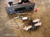
05 Dodge Caravan parasitic draw testing. I usually use my Vantage Pro on graphing multimeter mode to check a draw on a system, in my experience it paints a much wider picture of what is actually going on, and otherwise would be missed by the Fluke 87. Here is how I connected to this vehicle for testing [Parasitic draw testing]
I had mentioned in the reply it was about a 50% duty cycle, that is incorrect, it was late and I wasn't looking at the data at the time. I tried to get a reading on the duty cycle but couldn't figure it out, anyone know how to do this in amp mode on the vantage pro? I could figure it out math wise, just busy at the moment, and it is irrelevant at this point anyhow.
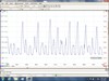
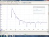
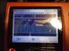
I checked draw with the Vantage pro in graphing mode [2005 Dodge Grand Caravan, BATT/Charging/Starting Waveform] see how it says 17mA, but then shows a rapid on off of amperage, on the upper left you can see it maxes out at 110 mA, this will drain a battery in just a few days. Here it is again with scope mode, [2005 Dodge Grand Caravan, BATT/Charging/Starting Waveform] . Here it is again with multimeter mode, [2005 Dodge Grand Caravan, BATT/Charging/Starting Photo] still shows 17mA with a peak of 110mA.
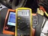
Here it is now with the Fluke 87 [2005 Dodge Grand Caravan, BATT/Charging/Starting Photo] shows 9.73 mA and I put it on min max, no real change, never went over 11mA.
I assume every tech on iATN would pass a 11mA reading I know I would. But without using a graphing multimeter you are only seeing a part of the story and not the part you need to see.
| |