|
30,000 Files and Growing
Scott Brown
The iATN Waveform & File Library continues to grow and has now exceeded 30,000 vehicle-specific files. The library actually contains an additional 22,000 files that are not flagged as vehicle-specific, but are nonetheless discussed in the iATN forums, which can be extremely informative. We look forward to improving the file library in every way in the near future: the number of file types supported, and the way in which they're uploaded, viewed, and searched.
Although most of the files uploaded throughout the years have been images, specifically waveforms, scandata, and photos, the file library now accepts video files as well. And it's incredibly easy to create a discussion in the forums about any videos you've uploaded. Video can be used not only to demonstrate something on a vehicle, but also to discuss scandata recordings, active scope data, set-up, and more. I've posted a brief video that explains one easy way to do this.
This edition of the iATN Review is packed with some highly regarded articles from iATN members, such as a nice tech tip when it comes to servicing the heater core on the new Camaro, Mazda timing belt woes, GM programming failure codes, and a cool tutorial covering GM's eAssist.
We hope you enjoy this edition, and if you have any questions about the newsletter, please post them to the iATN Development forum, or reply to this message to reach us directly.
Regards,

Scott Brown
iATN President

Short Summary of California's Recent Rulemaking
Industry Issues Forum
Mike from California
Given the other post on the ZEV mandate, I thought I would try and give the 2 cent summary on the ARB's recent rulemaking as it is pretty substantial and thought some folks would be interested.
ARB recently adopted the next round of tailpipe standards (LEV III) and zero emission vehicle requirements (ZEV program) primarily for the 2017-2025 model years. I have excerpted a few charts just to give you a general idea of what the requirements are (and no, I'm not the one with all the answers or know all the nuances of the why or how but I have what I'll call 'somewhat of an idea' about the requirements). For those that want to read more, there is plenty available here and from there you can get to specifics like the staff reports including executive summaries that are fairly easy to read for LEV III and for the ZEV program.
Ok, the short-ish summary. LEV III is the next wave of lower tailpipe standards. It covers both the traditional tailpipe pollutants (e.g., HC (known as NMOG) and NOx)). It also covers GHG (greenhouse gas) pollutants like CO2. Here's where tailpipe HC and NOx numbers will be going: [LEV III Tailpipe HC plus NOX]
Manufacturers will still be able to make cars at different emission levels (e.g., LEV, ULEV, SULEV, etc.) and the above graph is the 'fleet' average they have to meet each year (so they can sell say dirtier mustangs as long as they offset them with cleaner Fiestas and so on, just like they always have been able to do). It is new in that it will now be a combined HC + NOx standard instead of two separate standards to give manufacturers more wiggle room.
And for the GHG standards, here's a look that shows the last round and this new round and where the standards are: [LEV III Tailpipe GHG standard] Maybe it helps a little on GHG to look at this one that shows the same standards but also shows where 2008 model year cars and trucks currently are: [LEV III tailpipe GHG current]
The general premise is that there is a standard based on the footprint of the far (wheelbase times track width) and so bigger footprint cars can emit more but there are some tails to clip very small and very big vehicles. And there are separate standards for cars vs trucks. And yes, there are lots of credits and trading schemes that factor in as well but this still gives you a general idea where things are headed. The second one shows individual dots for every 2008 model year vehicle model and big dots for the average passenger car and average truck in the 2008 model year. It also shows dotted lines for the 2016 standard (that was previously adopted many years ago) and so you can see how much manufacturers have to move from where they were in 2008 to get their average below the dotted line for 2016. And then a solid line for where they need to get to by 2025 with these new requirements.
Ok, a second part of the rulemaking amended the ZEV program. As you probably all know, Calif has been trying to transition the fleet to ZEVs for quite some time because air quality standards dictate that essentially there be zero emissions from vehicles if we want a chance to actually meet the ambient air quality standards in the future. And, in 2003, the Calif legislature passed an Executive Order targeting an 80% reduction in GHG emissions (relative to 1990 levels) for the 2050 year. So, working backwards from what we need to have in 2050 to have an 80% reduction in GHG and meet ambient air quality standards (which is essentially 100% zevs in 2040-2050 timeframe), ARB proposed about a 15% target in 2025 to start the transition. Here it is graphically: [ZEV requirement]
And yes, eventually all ZEVs have to be what you think of as zero emission vehicles like battery electric vehicles (BEVs) and fuel cell vehicles (FCV) but in the interim years, you can still get partial credit for other things like transitional ZEVS (TZEVs) like plug-in hybrids which are 'zev-like' in some respects (e.g., some amount of all electric range, very low tailpipe standards, very low evap standards, etc.).
And I know folks like to bring up that zevs are not really zero emission because there are 'upstream' emissions (such as producing the electricity or hydrogen, etc.). And yes, the regulations all comprehend that and model that but I thought the following four charts might be of interest to those folks to see the relative magnitudes. These charts show various types of vehicles (e.g., current gasoline, future gasoline, plug-in hybrid, electric, fuel cell vehicle) and the relative amounts of NOx, HC, PM, and GHG from upstream ('fuel cycle') vs the vehicle (coming out the tailpipe/evap system) (or even A/C system for GHG). The 'WTW' acronym in some of the figures is 'wheel to well' as a term used to represent the whole picture. NOx, [NOx vehicle contribution], HC, [HC vehicle contribution], PM [PM vehicle contribution], and GHG [GHG vehicle contribution]
Probably pretty obvious to most folks but stationary sources (like power plants) are indeed easier to control emissions from than mobile sources (like cars) because you aren't as limited by size and weight and things like that. And, for those that don't know, Calif has a decently 'green' electricity generation grid (with not insignificant amounts of hydroelectric, natural gas, etc. in lieu of coal fired) and has pretty aggressive regulations to move the electricity grid to bigger chunks of these sources in the same time frames as these vehicle requirements. In any case, yes there are still emissions associated with making and transporting the electricity or hydrogen (for fuel cell vehicles) but it is generally substantially less than making and transporting gasoline and then having the vehicle emit too.
As I said, I'm not the guy making this happen and don't necessarily know all the ins and outs but thought I would frame it up a little bit for those that might be interested in knowing what happened recently.
Camaro HVAC Box Removal
Technical Tips Forum
James from Florida
Here's a tip for anyone who needs to R&R a HVAC box on a 2010 to 2012 Camaro for heater core, evaporator core or door repairs. For your first step, call the glass man and have him remove the windshield. At some point in your repairs, the windshield will need to come out as two very long bolts on either side run vertically into the support beam and cannot be pulled out as the glass is in the way.
If you have the glass removed first, you can work from the outside and inside and get it apart easier. After it's completly reassembled and tested, call the glass man back to reinstall the winshield.
Current Ramp for Blower Motor
Technical Theory Forum
David from Missouri
Hi All,
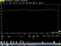
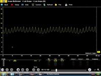
Just wanted to share these captures from a blower motor that I had come in the shop. The customer complained that sometimes the blower motor would not turn on. He further stated that he could "mess with the switch" to get it working again.
The blower was working when it came in. The customer complaint and description of messing with the switch, first led me to believe that there was a switch problem.
A simple current ramp test, done by clipping an amp probe around the wire at the blower connector under the dash revealed that the blower itself was worn-out. I captured both the original (worn-out) motor and the new replacement motor so everyone can see the difference. [2000 Chrysler Town & Country (Van) LX, Waveform] [2000 Chrysler Town & Country (Van) LX, Waveform] I simply used the same "preset" on my scope that I use to check fuel pump motors.
It's All About Timing
Technical Discussion Forum
Jonathan from Massachusetts
So here's a fixed car that I would like to share. It shows how important understanding computer inputs and how it relates to injector and spark sequence.
So here's a little back story to this car before it arrived in my bay. Vehicle had a timing belt, supercharger, and all oil seals replaced due to oil leakage. After being re-assembled vehicle wouldn't start.
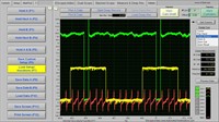
The first thing I noticed while cranking was it tried to kick back now and again like a distributor in 180 off. I'm thinking great this should be easy, a quick cam/crank sync search on iATN comes up dry. I pull cyl 1 plug (fuel soaked), drop a long screwdriver down the hole and roll motor to TDC. Once cyl 1 was at TDC I look at the crank pulley and verify its at TDC mark, good the key-ways intact and the crank pulleys on correctly. I then pull back the upper covers and check cam marks, hmm they're also correct. Now its time to hook the scope up and see what we can see, I grab cam, crank, and cyl 2 injector (easy to get to) and here's what i get.
[1999 Mazda Millenia S, ECM/Inputs/Outputs Waveform]
Now were getting somewhere. So we have 6 notches on the crank, one for each cylinder, and one reluctor on the cam to tell the ECM what stroke were on. The firing order on this car is a simple 123456 and I'm hooked up to the number 2 injector so why is it firing on the 3rd pulse after the positive cam pulse starts? Now its time to get invasive, I've got enough evidence to pull this engine down. Here's what i found.
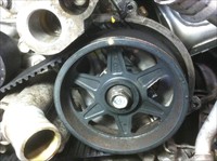
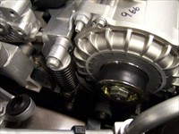
[1999 Mazda Millenia S, Engine/Propulsion Photo] The timing mark was dead on for both cams, the only problem is this car doesn't have to right cams! Note the R on the left bank cam. I pulled the belt left the timing mark lined up and flipped the gear over.
[1999 Mazda Millenia S, Engine/Propulsion Photo] Now its a left cam gear! Notice how when you flip the gear its roughly 9 teeth out of time. I put things back together, hooked the scope up and fired her up.
[1999 Mazda Millenia S, ECM/Inputs/Outputs Waveform] Notice now that the number 2 injector fires on the second pulse of the crank after the low pulse of the cam sensor. I hope this helps someone out in the future, if nothing else we at least have a know good cam crank sync for a 2.3 miller cycle engine. But it also shows how important it is to understand how the PCM uses cam and crank inputs to time spark and fuel sequences.
Chrysler Flash Availability Tip
Technical Tips Forum
Mike from Ohio
This may help someone with the process of finding a chrysler calibration. Im sure most of the seasoned guys out there already know this but it sure would have helped me out a year ago.
When you pull your Calibration from Mode 9 or what ever the route your scan tool takes you for particular module write it down, it should be a series of digits ending in AA AB AC and so on. Click on the link which is at the bottom of Techauthority under related documents and links. Here is the actual link.
Depending on what version of adobe or windows operating system sometimes you will see in the left column a pair of binoculars click on that and put your current Cal in there and it will search and find it for you. If you don't see the search options you can try to hover your pointer around the bottom of the page and a bar should pop up click on the adobe sign or icon to the far right and that will bring you to that search window.
The columns tell you about the vehicle , type of module, old calibration # ,new calibration# and TSB # If you have one of the Calibration # in the old column then you have an update available.
If you have a non comm. module and can not get the old number its going to be a pain to ID the thing and pick the right Calibration. Im hoping someone reading has a tip for that =).
PS you can use the search when you have a TSB # or Cal # and copy and paste are your friend when searching from another source be it Mitchell , Alldata , Identifix, or OEM.
HTH and if anyone has anything to add please do I found this process kinda confusing at first.
Fuel Pump Testing
Technical Tips Forum
Russel from Arizona
Had a ranger fail to start a couple days ago in a neighboring town. A shop there said it was a bad fuel pump. As I found out, it had failed to start about a month ago also but with the "final try" it started.
When it got off the tow truck it started normally. Fuel pump amp scope had one segment that was not like the rest but it was putting out 60 PSI running with 7-8 amps.
Looking in the archives I found several posts of intermittent fuel pump caused no starts. But this pump was 4 months old, from Ford, so how to prove the pump failure for warranty. There was a reply that made the proof possible. I thank the person who told how to use a remoter starter switch in place of the relay to turn the pump on and off repeatedly while scoping. Doing so let me capture the fail of the pump to spin several times, shown by the spike to 19 amps.
A nice method for intermittents.
G.M. Programming Failure Codes
Technical Tips Forum
James from Florida
Occasionally when you program a G.M. module, you may have a failure. At this point an E-code will be displayed. Usually there is no definition of this failure other than the code. Here is a list of the most common failure codes.
E4398 - no Calibration Data - the calibration data is not loaded onto G.M.'s server - you need to cotact Techline for a VCI number or a calibration update.
E4399 or E4403 - Severe Error - loss of communication between the programming devive and module - ck connections and battery voltage. Programming communication speed may be too fast for the module.
E4413 or E4414 - non recognized calibrations or calibrations marked with an * - restart programming and select "Replace and Reprogram"
E4404 or E4494 - loss of communication brtween the programming device and Techline
E4491 or E4423 - Programming Failed - incompatibility between the software/calibrations and the module - contact Techline
2012 Buick LaCrosse eAssist
Technical Theory Forum
Martin from British Columbia
Hi all. During the past week, I took the opportunity to attend training on the 115 volt GM eAssist system as currently fitted to 2012 Buick LaCrosse, which will also find its way into the Chevrolet Malibu for 2013 MY.
At a glance, we might consider this just another Belt Assisted System (BAS), but while there are obvious similarities there are a number of notable and subtle differences, besides the obvious higher voltage rating that separate this system from the earlier system.
We can expect to see more electric drive systems incorporated into a wider cross section of GM vehicles in the future, so taking a look at developments as they occur and sharing here, is worthwhile.
The previous BAS, while a mild hybrid, did serve a purpose in reduction of CO2 and other vehicle emissions during auto stop events and experiences have been drawn from that and other hybrids, as each step forward presents the opportunity to develop, or improve on certain technologies.
The eAssist is available on the LaCrosse in Canada, to models fitted with 2.4L LUK Ecotec engines and 6T40 automatic transaxles. There is no external or internal badging on the vehicle to identify that this is any form of hybrid, which may make for some interesting experiences where highway lanes and parking areas are available for use of hybrid vehicles. The main components of the system are a Hitachi liquid-cooled motor generator unit, similar in outward appearance, but larger than in previous BAS models and the controls which are all housed within the battery container, unlike previous systems of this general design.
Regarding the controls, wiring schematics will show a number of dotted lines that signify a part of a component is being displayed. In the case of the eAssist, there will be a a number of modules that are circuit board mounted and depicted by dotted line rectangles, within one or two more rectangles. Therefore, when programming is required, rather than HPCM, MCM and APM being available in a pick list, these components are incorporated into the (Starter)Geenerator Control Module. The Battery Energy Control Module is a separate silver box, mounted on the battery assembly, so expect to see BECM and GCM in SPS. I have not confirmed this, but that is how it was explained to be at this time.
There has been a shift from using the term "BAS" to "eAssist" for good reasons. There is more power available with the 15KW induction motor generator at 115 volts, for assistance when accelerating hard or negotiating steep hills. As in previous versions, the system incorporates auto stop and start capability, with deceleration fuel cut off and extended periods of lock up torque converter apply.
The motor spins the engine over during deceleration cut off, to provide regenerative braking. Other now familiar terms such as "torque smoothing" are used to describe the transitions from engine on to off and vice versa, during decel and auto start. With the belt removed, GDS2 can be used to spin the motor to ensure that it is free. While we can spin the motor by hand, using the scan tool might be useful if addressing a bearing noise concern. [2011 Buick LaCrosse CX, Photo] [2011 Buick LaCrosse CX, Photo]
A 115 volt Lithium ion battery pack is mounted in the same location between the rear wheels directly behind the rear seats inside the vehicle trunk. The battery and control system is air-cooled and air from the vehicle cabin is drawn through a grille in the rear "parcel" shelf through the battery and into the trunk. Here is the motor [2011 Buick LaCrosse CX, Photo] and the air intakes for each of the spiral wound Lithium ion battery packs. [2011 Buick LaCrosse CX, Photo]
Unlike the previous BAS system, there is no Starter Generator Control Module (SGCM) mounted up front in the engine compartment in a housing that resembles and performs inverter and various other functions. All controls are incorporated into the metal housing that contains two sixty volt Lithium ion batteries, along with now familiar hybrid control modules, pre-charge resistor, pre-charge contactor relay, Generator Control Module (GCM), Battery Energy Control Module (BECM) and much more.
Repair by technicians is anticipated, since we explore the innards of the battery energy storage system here in the photos as some preliminary procedures were performed.
From the manufacturers' names on the various modules and components, it can clearly be seen that this components are sourced from many manufacturers and locations around the globe by Hitachi. The whole assembly weighs in at approximately 65 lbs, so while it isn't particularly heavy, we need to be careful when removing the assembly from its mounting location.
Mounted directly to the battery housing is an electric motor, much like most fans used in motor vehicle HVAC systems. This system draws air through grille in the vehicle passenger rear compartment shelf, through ductwork and into the trunk. I can imagine a customer concern of "The tissue box on my rear parcel shelf empties itself!"
As with other hybrid applications that are rated as high voltage (>60v), following precautions by using required Personal Protective Equipment (PPE) is necessary is something that we all need to become more familiar with and practice until it becomes "second nature." apart from recognizable high voltage decals, systems with high voltage also carry the high voltage symbol, represented by a triangle with lightning bolt. [2011 Buick LaCrosse CX, Photo]
The vehicle components in the engine compartment, trunk and undercarriage all carry warning decals and instructions. Most notably, red warning labels indicate that high voltage is present at all times and orange labels identify that high voltage may be present. Unless the voltage has been measured and verified to be at safe levels for service outside the battery container, it is wise to always assume that high voltage is present. In the event that a contactor is stuck closed, this could be the case. The battery case contains two batteries that approximately ½ fill the container at the passenger (right side) of the vehicle the rest of the High Voltage Energy Storage system container is occupied by control modules, cables, contactors, current clamp and other aforementioned pieces.
Required tools for diagnosis and service, include Fluke 1587 or equivalent and is not considered to be an essential tool, but a necessary tool. In other words, GM isn't providing the tool to servicing dealers of eAssist or Volts. However, the cost should be borne by the servicing dealers, rather than the technicians.
The Fluke 1587 is required for Loss Of Isolation testing and GM does recommend wearing the high voltage electrical gloves when using the meter.
An aluminum conduit carries the three phase cables from the battery module, down through the trunk floor, under the vehicle and to the motor generator unit in the engine compartment. Being a belt assist system, there are some familiar but slightly different tensioning system components to the previous BAS systems. The same belt tensioner holding tool is used.
As in other hybrid systems, the hood latch plays an important role, especially so in the system, since the system does not charge the battery when the engine is running and the hood is open. This vehicle does incorporate "Jump Assist", which may be familiar to some of you who have worked on or learned the term from the GM 2 mode hybrid systems. However, in this application, there is no scan tool required to initiate jump assist, notably because this is a global vehicle platform for which the Tech 2 and Tech2Win, serve no useful purpose.
At this point, at least in Canada, batteries and/or components are serviced on an exchange basis only at this time. However, since training has technicians removing and opening up the battery storage system and the fact that part numbers are attached to many of the internal components, it is reasonable to assume that there will be a point where technicians will replace individual components.
Disabling the system is similar to other hybrid systems, where the key(s) must be removed to specified distance from the vehicle. Note that this system is apparently available in both key start and PEPS push button start versions. Disconnection of the 12 volt battery and waiting 5 minutes for capacitors to discharge is a typical routine in disabling systems, as is the used of "Live, Dead, Live" verification of confirming voltmeter functions and measurements at battery terminations in the trunk.
While the instructions use the term "manual disconnect lever", there is no actual "lever" involved. The purpose of removing, or positioning manual disconnect switches and levers is generally to separate battery packs into smaller units of lesser voltage and this application is no exception. To disconnect the batteries from one another, locate the greyish appearing sliding "switch" mounted to the front of the battery container, behind the right rear passenger seat back. Pull the small blue CPA tab out slightly. It will click into position. To the right side is a small grey button, referred to as "white". Depressing this button, will allow the switch to be slide sideways, opening the manual disconnect circuit and separating the two batteries. [2011 Buick LaCrosse CX, Photo]
In past, GM hybrid vehicle system High voltage Interlock Systems (HVICs) have been switches connected to a 5 volt series circuit. The purpose was and continues to be to shut down the system in the event of uneducated tampering or untrained attempts to diagnose the systems. The interlock in this particular system, contains a resistor, which I recall is approximately 3K Ω. So, rather than a simple switching circuit, it is now a sensing circuit, where information can be analyzed by the controls and an appropriate DTC set.
The Hitachi MGU differs from the BAS system, by way of being liquid-cooled, using a mix of DexCool and drinkable tap water. This is not a dedicated cooling system, rather it is a loop added to a conventional cooling system, with pumps added for coolant circulation and heater circuits.
Inside the battery case, voltage can be anywhere from 0 volts to 120 volts, depending on the condition of the components, level of charge and more. Once the manual disconnect process has been completed, the batteries should be isolated from each other, but may not be in the event of a stuck contactor as mentioned already. Regarding contactors, previous high voltage hybrids such as the 2 mode used three contactors, a pre-charge contactor, positive and a negative contactor. The 115 volt eAssist (sometimes referred to as BAS +) utilizes two contactors. One serves as the pre-charge relay and the second is the positive contactor. Engineers decided that a negative contactor is not necessary.
Inside view of the battery container lid, shows clear insulation material as bordered in red [2011 Buick LaCrosse CX, Photo]
Moving to view the components with the lid removed and PPE (1000volt gloves currently certified, physically inspects, safety glasses with side shields, CSA rated footwear, recommended non-flammable clothing, jewelry, watches, pens removed etc) [2011 Buick LaCrosse CX, Photo] What cannot be seen in the photos are the battery strap connections to the Generator Control Module (inside silver box) under the relay centre.
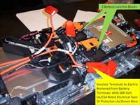
Replacement of batteries will require removal of battery cables from each battery terminal at each battery cable junction block , using insulated tools and step by step insulating each cable with 600v UL/CSA rated electrical tape and/or insulators as in the photograph [2011 Buick LaCrosse CX, Photo]
Here is a close up of the pre-charge resistor that measured approximately 3K Ω current clamp, pre-charge contactor relay and positive contactor. There is no negative contactor. [2011 Buick LaCrosse CX, Photo]
Here is a close up of the fuse, manual disconnect, which is not actually a lever and the high Voltage Interlock Circuit (HVIC). [2011 Buick LaCrosse CX, Photo]
Here is a view of the battery cable junction blocks [2011 Buick LaCrosse CX, Photo]
With access to the Battery Energy Control Module (BECM) connectors X4 and X5, each battery pack can be tested using the test harness and the same tool El 48571 as previously used for 2 mode battery testing [2011 Buick LaCrosse CX, Photo] Connecting the X4 and X5 harnesses to the adaptor harness, allows each battery cell to be tested and voltage recorded. This will verify scan tool displayed values. [2011 Buick LaCrosse CX, Photo]
For a tour of the eAssist system, I recommend viewing videos posted to Youtube by John Kelly of Weber State University Automotive Department in Ogden, Utah.
You may John's other videos interesting.
http://www.youtube.com/watch?v=ByAQvuzcTq8 and http://www.youtube.com/watch?v=n2NQ_dO3lMU
http://www.youtube.com/watch?v=7JvHT23ubHs is not from Weber, but is an animated overview of power flow relative to road speeds.
Regards,
| |