|
A New Look
Scott Brown
As some of you may have noticed, iATN has a new look on the public side of the site. Right after the first of the year, we introduced two new public facing websites. The main public site has a cleaner, more concise representation of the features available to iATN members. Now when you refer a colleague to iATN, they should be able to learn more about what's available in short order. Our other site is aimed at vehicle owners, and presents the new Auto Repair Shop Finder designed to help drive more traffic to Business Premium Members of iATN. The new geo-locator can use your browser or computer location, or you can input an address, city or zip to help quickly locate a repair facility.
For members that are logged into iATN, you will notice that the map center defaults to your registered address with iATN, to quickly display a list of shops near you. Additionally, the Auto Repair Shop Finder is mobile-friendly, so be sure to check it out on your smartphone to see what a potential customer might see.
The first 2012 edition of the iATN Review is once again packed with highly-rated messages posted throughout the network during the fourth quarter of 2011. In this issue, we have an interesting post covering the Chevy Volt with multiple images, some excellent technical tips covering the Duramax LB7, Malibu Hybrid, and some cool VW/Audi tips as well.
We hope you enjoy this issue, and if you have any questions, please let us know!
P.S. From March 8-11, I'll be teaching an iATN training session called "Mastering iATN" at the 20th annual Vision Hi-Tech Training & Expo this year in Overland Park, Kansas. iATN will also be hosting the Industry Professionals Reception on Saturday night. I hope to see you there! For more information please visit Vision's website.
Regards,

Scott Brown
iATN President

Volt Features
Technical Theory Forum
Martin from British Columbia
Recently, I had the opportunity to audit a Chevrolet Volt battery diagnosis and safety course. Since I always have a camera handy, I snapped a few photos along the way and have posted them here for your interest. My aim is to show you some of the stuff that isn't shown in the fancy photos taken from a distance and provide a few details.
This post is intended only as an introductory FYI topic of interest to describe a few of the electrical features as they relate to battery safety and diagnosis. See the service manual for in-depth step by step procedures and always follow Personal Protective Equipment and tool requirements and observe all safety precautions and labels.
Since the vehicle has been available in USA as a 2011 model and more recently in Canada as the 2012 model, if you ante up for a short term subscription to GM electronic service information at www.acdelcotechconnect.com [acdelcotechconnect.com] , you can read up on how the various systems function and learn about the diagnostic procedures and system tests. Rely on the expertise of GM dealer technicians for their encounters with this vehicle, James Avery in particular having posted some useful and interesting case studies to date on programming issues. Sorry if others have posted some good stuff, that I have missed.
With the technological advances being made daily, there's not a lot of room for "nuts and bolts" only technicians these days, so if you're the slightest bit intimidated by technology, its probably a good time to consider your next career move, before it is mapped out for you by someone else. If you're not faint-hearted, embrace the technology and climb aboard as the future that Jim Wilson and others warned you about is here and already marching on to bigger and greater things. All manufacturers have advanced technologies that are demanding high levels of diagnostic expertise. If you're not interested you might as well give up now or make plans.
As with any electric vehicle or hybrid system, when servicing specific components or areas of the vehicle, it is necessary to disable the high voltage energy storage system. The methods and needs vary from one vehicle to another, depending on the area of service. Refer to GM SI document #2409469 for the complete description of disabling and re-enabling the high voltage system and observe all warnings and caution labels.
There are many links to Volt First Responder Guides as posted on the GM Service Technical College website can be stumbled upon by doing a simple search. Here is one result http://www.evsafetytraining.org/resources/auto-manufacturer-resources/~/media/Files/PDFs/VoltRespondersGuide.pdf [evsafetytraining.org] that provides some nice photos and general descriptions of the component locations within the vehicle. My photos will provide a little closer look at actual connections and some of the key components. Refer to service information for actual or complete procedures.
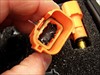
Here is a photo of the Manual Disconnect Plug, identifying the main and charger interlock circuits to the front and rear of the plug, respectively. [2012 Chevrolet Volt, BATT/Charging/Starting Photo]
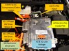
A pair of jumper harnesses are required to make connections for testing at the Battery Junction Block under the vehicle at the front of the battery pack.
[2012 Chevrolet Volt, BATT/Charging/Starting Photo]
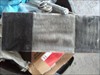
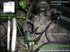
Here's a "fuzzy" photo of the under car access once the exhaust and heat shield has been removed. Not shown is the rear of the cradle that borders the photo and restricts ease of access. [2012 Chevrolet Volt, BATT/Charging/Starting Photo]
Read the entire article here.
Duramax LB7 White Smoke Diagnostics
Technical Theory Forum
Ryan from British Columbia
Recently in the Heavy Duty/Fleet forum there has been discussion about white exhaust smoke on these engines at idle. When injectors are the root cause of this issue, they are allowing too much fuel to enter the cylinder over too long a period of time. This is a mechanical fault of the injectors which the PCM can not account for and why no codes are generally set.
If a technician connects to the vehicle and performs all related tests they may find cutting out one or more cylinders may cure the smoking issue but they are also adding more load to the the remaining cylinders which can give a false result. If the entire set is warn however this may not work and leave the technician at a loss. Two PIDs that are commonly over looked in these cases are "Calculated Fuel Rate" in mm3 and "Injector Command" in ms.
Below is an example of a smoking truck's balance rate with several warn injectors.
Cyl.1_ 0.1mm3
Cyl.2_ -1.0mm3
Cyl.3_ 2.5mm3
Cyl.4_ 1.3mm3
Cyl.5_ 2.5mm3
Cyl.6_ -1.6mm3
Cyl.7_ -3.0mm3
Cyl.8_ -0.8mm3
In the above example no injectors are falling out side of the +/-4mm3 limit set by GM at idle. Some may flag #7 right away for being close but lets look at this in a little more depth. Do you notice that the average of the all eight injectors equals zero? The real question is what figure are these balance rates zeroed to?
This is where the "Calculated Fuel Rate" comes in. On the truck in my example this figure is 3.0mm3. When you apply this figure to the balance rates you get the calculated fuel rate for each injector.
Cyl.1_ 3.1mm3
Cyl.2_ 2.0mm3
Cyl.3_ 5.5mm3
Cyl.4_ 4.3mm3
Cyl.5_ 5.5mm3
Cyl.6_ 1.4mm3
Cyl.7_ 0.0mm3
Cyl.8_ 2.2mm3
Now you can see a much clearer picture of what is really going on. A new set of injectors will run around 5.0mm3 at idle, on a warm engine. Injectors 1-2-6-7-8 are commanded to deliver less fuel because they are faulty. The other method of catching this fault is by watching the "Injector Command" PIDs.
Inj 1_ 0.29ms
Inj 2_ 0.26ms
Inj 3_ 0.37ms
Inj 4_ 0.34ms
Inj 5_ 0.37ms
Inj 6_ 0.24ms
Inj 7_ 0.14ms
Inj 8_ 0.27ms
I have found that any injector running under 0.30ms will lead to the white exhaust smoke in question. It is always a good idea to watch your rail pressure when checking all the above PIDs as higher than normal pressure will cause the injector delivery rates to drop in an attempt to maintain idle speed.
One variable in this situation is the engine itself. The PCM is trying to balance each power stroke of the engine for the smoothest possible idle. Engine compression and what is happening in companion cylinders can have an affect on these readings.
I would not use this information to only replace the injectors deemed faulty. This truck received a set of injectors because five where faulty but I could not say that the remaining three were any good. This may come in handy when a customer does not want to replace an entire set due to the expense. I have found however that replacing the worst bank can fix the issue for a period of time until the other bank deteriorates further.
2009 Malibu Hybrid with a P2797
Technical Discussion Forum
James from Florida
This was an interesting failure that came in the other day that most techs have probably not seen. This Malibu Hybrid came in with a complaint of auto-stop inoperative and Service Hybrid System message on. The only code set was a P2797. It was set as a hard code and would not clear. This code is set when the auxiliary transmission fluid pump is commanded on during auto-stop and the TFP switches do not indicate the fluid pressure increase from the running pump. Since the pump running is necessary for auto-stop, it is disabled when this code is set.
If you ever look at the S.I. diagnostics for this code, they are a total joke and unusable. There are two tests that can be performed with the Tech 2, you can command the relay on or you can command the pump on. The relay on test works, but the pump on test does not as the Tech 2 cannot command the pump on although this test is offered.
This pump does not operate as most relay controlled devices do as neither power or ground are provided to the pump at all times while the relay switches either on or off. The power circuit to the pump is switched on and off by the relay which is controlled by the SGCM and the ground circuit is controlled by the Hybrid Pump Driver Module which supplies a PWM ground to the pump.
The easiest way to test this circuit is to first unplug the HPDM and supply power and ground to the pump through ckts 7435 and 7436. If the pump runs and the TFP A parameter switches from low to high, the hydraulic portion of the circuit is OK. Next, command the relay on with the Tech 2 and see if 12 volts is supplied to the pump through ckt 7435. If so, with the HPDM plugged back in, unplug the X1 connector at the SGCM. Remove the relay and jump across the connectors with a fused jumper to supply power to the pump. Supply power to the HPDM with another fused jumper at terminal 1, ckt 7439. Hook a test light to battery positive and rapidly tap terminal 15, ckt 7438 with the test ligh to simulate a PWM command from the SGCM to the HPDM. The pump should run. If not, the HPDM is at fault. If it does run, the SGCM or either connector or wiring is at fault.
With my vehicle, the pump did not run during this test and the HPDM needed to be replaced. This resolved the complaint.
Fuel Trim Experiments
Technical Theory Forum
Patrick from Virginia
It amazes me how Albin and Darrell and others can use fuel trims to diagnose misfires. I am trying to learn these procedures so have been experimenting. To start out, I am not sure I fully understand the difference between LT and ST.
Initially, I thought LTs were larger increments like "Hours" and STs were smaller increments like "minutes". So a Positive LT of 16 (lt +16) and a negative ST of 10 (ST -10) would be greater than a LT +15 but less than a Full LT of +16. (kind of like 10 minutes before 16 o'clock.)
But over the weekend I have been doing some reading and now it looks like a LT increment is the same as a ST increment, just the computer has different ways of getting there. For the sake of ease and clarity, I will say that 1 fuel trim = 1ms of injector on time. If this is the case, than a LT+16 means the PCM will add 16ms to injector On Time. But with a ST of -10, it would subtract 10 ms of injector On Time so in all actuality the Injector would really only receive 6ms of additional On Time, (+16(LT) - 10(ST) = +6)
I also did some experimenting with my 95 Buick Park Avenue with 3.8
My MODIS doesn't list Long Terms and Short Terms on this vehicle. It lists Long Terms and Fuel Trims. So I will use those terms here in this discussion.
Starting out my LT was 132 and the Fuel Trim was 130.
Next I disconnected my fuel injector.
My LT stabilized out at 149 and my fuel trim was at 131. Thus if I understand this correctly, the O2 responded with too much oxygen so the pcm responded with longer Injector On Time to balance out the extra Oxygen in the exhaust stream.
Next I plugged back in my Injector and disconnected my spark plug wire (I hooked the wire to a spark plug checker so that it would not affect the other companion cylinder.) My LT stabilized at 146 and my ST was at 127. It looks to me like the extra air that wasn't burned in the cylinder still resulted in extra injector on time, but not quite as much as with the injector unplugged. So maybe the unburned fuel in the exhaust stream skewed the O2 readings to be just a little lower than if that unburned fuel wasn't there.
Next I plugged back in my spark plug wire and disconnected the vacuum line to the fuel pressure regulator. (I did block off the vacuum line so I wouldnt have a vacuum leak.) My LT stabilized at 136 and my fuel trim at 131. This reading surprised me because I expected my LT to drop below the initial LT of 131 because higher rail pressure should cause more fuel dumped for same injector on time. So I expected it to be rich and the PCM to compensate with shorter injector on time.
Next I plugged back in the fuel rail and dissconected the vacuum line to the Cruise Control Module to induce a vacuum leak. This resulted in a LT of 140 and a Fuel Trim of 131. Again it looks like extra / unmetered oxygen in the exhaust stream means the PCM will correct by increasing Injector On Time.
I noticed that my fuel trim would always stabilize at about 130 or 131. Initially after inducing a fault my fuel trim would adjust rapidly, then the LTs would catch up and adjust themselves until my fuel trims were able to maintain just around 131. So I am thinking that GMs like a fuel trim of 131 and will adjust the LT until it can maintain the 131 on the fuel trims.
Any idea of what experiment I could try that would result in lowering my LT of 131? I really expected the fuel pressure regulator being disconnected to do it but it didn't.
Thanks for any replies in helping me to learn this. The next time I get a ford product in the shop I am going to try this same experiment.
TDI Camshaft Wear Warning Signs
Technical Tips Forum
John from Ontario
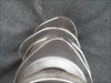
This applies to VW pump duse TDI engines, I thought the group might find this interesting. The 04 to 06 VW tdi's have been known to wear the lobes off their camshafts, usually as a result of not using the proper 505.01 spec engine oil. The first warning sign is usually soot in the air filter, but no particular driveability symptom. [2006 Volkswagen Jetta TDI, Engine/Propulsion Photo] [2006 Volkswagen Jetta TDI, Engine/Propulsion Photo] This could be picked up at a routine service. As one or more exhaust lobes on the camshaft begins to wear, lift is reduced, but the exhaust valve still opens. No noise is present because the engine has hydraulic lifters (with remarkable ability to pump up and maintain valve clearance).
As the condition deteriorates, sometimes odd MAF codes are stored, "implausible signal" etc. Exhaust cannot exit the cylinder fully because the valve is barely opening, so there is some reverse flow into the intake the next time the intake valve opens. It all hits the fan once the top of the lifter gets a hole worn through it. At that point the lifter collapses and the exhaust valve doesn't open at all. The four stroke cycle becomes three- intake, compression, power, and nowhere to go... followed by pow! back through the intake plumbing and intercooler. Here are pics of a worn cam lobe and a relatively good lobe [2006 Volkswagen Jetta TDI, Engine/Propulsion Photo] [2006 Volkswagen Jetta TDI, Engine/Propulsion Photo]
The car in question actually drove in with almost 1/4 inch of lift missing from an exhaust lobe and was backfiring into the intake when given throttle. If you see significant soot in the air filter, you may want to suggest inspecting the camshaft before broken pieces of lifter start floating around.
Seeing The Whole Picture: The Importance of Loop Status
Technical Tips Forum
Matthew from Illinois
This Ford van came to me with the typical P0171 and a P0174. [2001 Ford E-250 Econoline, Scan Data] OK, so it's time to analyze fuel trims. Whenever I look at trims I always pull up the Fuel System Status. I see many screen shots posted here without this pid displayed. Hopefully with this post I can prove how important it is when looking at fuel trims.
First I need to briefly explain the different fuel system statuses. We should all know what closed loop and open loop are so I will not spend any time on them.
Open Loop - Drive, also known as fuel enrichment, occurs during heavy acceleration and WOT.
On a two bank vehicle Closed Loop - Fault is when one bank O2 sensor or A/F sensor has a fault. This can be caused by a bad sensor or by one bank being extremely rich or extremely lean. The vehicle will then substitute fuel trim corrections from the "good" bank to the bank it believes has a fault.
Open Loop - Fault is when both upstream oxygen or A/F sensors on a two bank vehicle have a fault. This could be caused by two bad upstream O2 sensors or both banks can be extremely rich or extremely lean. On a single bank vehicle Open - Loop Fault occurs when the upstream sensor has a fault. This could be caused by a bad upstream sensor or the vehicle is extremely rich or extremely lean
OK, enough of the boring stuff, back to the case study. Luckily this van came in the night before and the engine is cold. I do a cold start and watch the fuel trims. Here is what I saw when the vehicle is in Open Loop. [2001 Ford E-250 Econoline, Scan Data] Shortly after start up the vehicle goes into closed loop. [2001 Ford E-250 Econoline, Scan Data] Notice that the total trims on both banks starts to climb towards +40% on both banks.
Not long after the vehicle goes into Closed Loop it then goes into Closed Loop - Fault. [2001 Ford E-250 Econoline, Scan Data] Notice that the STFTs and LTFTs on B1 and B2 are exactly the same. If I didn't know the vehicle was in Closed Loop - Fault I would be pretty confused about what was going on with the trims right now. At this point the vehicle starts to surge a little bit.
Not much longer and the vehicle now goes into Open Loop - Fault. [2001 Ford E-250 Econoline, Scan Data] At this point the vehicle has a rough idle and is surging because all of the positive fuel correction has been completely taken away from it. A quick glance of fuel trims without looking at fuel system status at this point could take you down the wrong diagnostic road.
After the vehicle finally gets to full operating temperature it goes back into closed loop and runs well. [2001 Ford E-250 Econoline, Engine/Propulsion Scan Data] I then bring it up to 2500 RPM [2001 Ford E-250 Econoline, Scan Data] . It's pretty obvious at this point that I have a vacuum leak. Within 15 minutes of running this vehicle I know have a pretty good direction before I even pull the dog house.
Upon further inspections I found that the upper intake manifold gasket was leaking. I just wanted to make everyone aware of how important it is to look at the fuel system status to get the "big picture".
P0455 Gross Leak 1999 Audi A6 Quattro
Technical Tips Forum
Danny from California
Hi TTiF,
I recently had a customer come into my shop with a vehicle that failed it's bi-annual Smog Inspection. The vehicle failed the OBDII Functional Test for a lit MIL and a P0455 Evaporative Emission System Gross Leak.
There aren't a lot of Volkswagens or Audis in my neighborhood, and this is the first EVAP failure I've ever done on this type of platform.
I started by verifying the integrity of the gas cap with my Stant gas cap tester. It uses pressure to test the cap, which is good since the Audi uses a Leak Detection Pump to test the EVAP system for leaks. The gas cap tested good.
The next step I took was to run Basic Setting 070 and 071 with my ProDiag Palm Scanner. It passed the 070, but failed the 071.
To me the obvious thing to do next is to look for a leak in the gas tank and canister. I isolated the tank and canister from the purge and vent hoses, put my flow meter on the filler neck and found no leak. That was a lot of work for nothing.
I looked in the iATN TechHelp Archives and I found a response that said to pinch the hose coming from the Canister Purge Control Valve and run Basic Setting 071. If it passes the test, you've found your bad component that caused the P0455 to set. I went back into the archives, but I couldn't find the response to give the tech credit for this tip.
[1999 Audi A6, Emissions Photo]
It worked. I replaced the Canister Purge Control Valve, ran the 071, the light went out. I performed the Smog Inspection and issued a certificate.
International Full Power ABS ECM Replacement Procedure
HD/Fleet Forum
Joshua from Maryland
Just found out myself and figured I would share in case anyone else has this issue.
I replaced and programmed the ABS ECU and got a constant blinking ABS light with no codes, called Meritor and they let me know of a secret menu to stop the blinking light by setting status.
So here it is:
When replacing a ECU on a Full Power ABS System.
Perform the following
1. Replace ECU
2. Open Meritor tool box, go to HABS
3. Log into International ISIS
4. Locate Meritor FPB programming in the menus on the left side
5. Enter last 8 of VIN and download file
6. Under parameters in toolbox select write parameters, your VIN should show up in the box, hit "download"
7. Hit and hold control, shift, alt then tap F12, this will show you a hidden menu "utility"
8. Select check status, then hit "set status" this will stop the blinking and act normal.
Failure to "set status" will cause the ABS light to flash constantly and not set any codes in the ABS or ESC and in my case go crazy!!!!
Just as another note, the ECU is available separate you do not need to buy an entire control unit, I had international telling me I could only buy an entire unit for $1800 when the ecu is available and $800
| |