|
75,000 Strong
Scott Brown
iATN crossed a milestone this past quarter when the active membership exceeded 75,000, pushing our combined experience to over 1.75 million years! That is quite a remarkable measure that you can take advantage of by simply participating in many of the various areas of iATN. With your membership, you have access to a vast array of industry knowledge. Thank you to everyone that participates on iATN!
As you may know, we conduct a member poll on the members-only homepage every month or two, and generally get tremendous feedback. Our latest poll on scan tool form factor preferences was no different, with over 4,000 respondents, 775 of which left comments to expand on their poll choice (view the results). Our current poll asks about WiFi access in the repair shop, and all polls are archived for your reference.
In this edition of the Review we have highlighted several highly-rated posts by iATN members, which include a tip about repairing DLC Terminals, Ford IDS Triggering, MAF Sensor Analytics and a look at CAN from a new perspective. We hope you find these interesting and useful!
As we head into the fourth quarter and round out the year, all of us here at iATN wish you and your families the best. We are very excited about what is in store for 2012! Stay tuned by following the latest iATN News via your preferred service: Facebook, Twitter, Google+, or RSS.
Regards,

Scott Brown
iATN President

Low Cost COP Ignition Pickup for Pico Scope
Tool & Equipment Forum
Martin from New Zealand
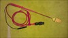
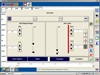
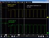
For those who have a Waekon 76562 COP ignition tester, it can be converted very to make a very impressive COP tester for your scope, I have tested it on a few cars and found it very good, You may have one of these in your tool box and can revitalize it buy connecting it to your scope. I connected it via a 20:1 Attenuator for safety and a spare Scope lead as you can see in the pictures. I have found the probe is not temperamental as to where I place it on the top of the coil, which I found with the PICO supplied COP Tool. The Pickup antenna and rod can be purchased as spare parts from Waekon for about $20 (so they have told me), I called Mario at AES wave about making up a kit to supply every one so will have to call him to see how he is going with it. [Waekon COP with 20:1 atenuator ( Home Made)] [2001 Lincoln Town Car Executive, Ignition Waveform] [2001 Lincoln Town Car Executive, Ignition Waveform]
Good luck and hope you enjoy
6.0L Misfire with Injector Circuit DTCs
HD/Fleet Forum
Robby from Alabama
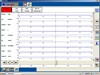
This ambulance came in with a running rough concern. I first pulled DTCs and found P0262 & P0265 (#1 & #2 injector circuit high). I performed a KOEO Injector Electrical self-test got this: [2005 Ford E-450 Super Duty, ECM/Inputs/Outputs Scan Data]
This is the power balance: [2005 Ford E-450 Super Duty, ECM/Inputs/Outputs Scan Data]
FICM voltage PIDs: [2005 Ford E-450 Super Duty, ECM/Inputs/Outputs Scan Data]
I looked up the pinpoint test for the DTCs. The testing involved checking the suspect injector for circuits shorted to each other, injector circuits shorted to ground, injector circuits shorted to power, and suspect injector coil resistance. All of the steps passed and the pinpoint test directed to replace the FICM.
I've encounter this issue before. I've replaced FICMs for this very issue because that's what my diag steps led to. However, in the past, the $700.00 FICM did not fix the concern. I rarely see a FICM fail on an E-series. Usually, on a E-series, some issue with wiring harness or injector was the cause.
The 6.0L injectors have an Open Coil & a Close Coil. These coils control the position of the spool valve inside the injector. These injectors also operate at around 48 volts. In my experience, these "high voltage" systems are more sensitive to circuit failures than what I'm used to at battery voltage level.
Per the pinpoint tests, circuit checks are performed by using an Ohm meter. I'm sure we all know how accurate that can be. An ohm meter can be useful and does have its place, but you also have to understand those "tests" do have their limits. Both injector coils have a resistance spec of 0.4 - 0.6 ohms at ambient temp (which is the temp my testing was done). Unfortunately, I have an injector circuit fault on the most difficult injector to access. Fortunately, the FICM is easy to access on a E-series. Here it is: [2005 Ford E-450 Super Duty, ECM/Inputs/Outputs Photo]
My circuit tests was done at C1388a. From there, I can measure the entire resistance of both #1 injector circuit coils. I measured 0.7 ohms. This technically is out of spec, but I'm also testing resistance of additional wiring. I compared this to a normally functioning injector (#6) and measured the same thing. So now is the time to try something different.
I looked through the waveform archives to try and find known good injector waveforms; I didn't come up with much. I started by testing a known good injector, #6.
Open Coil: [2005 Ford E-450 Super Duty, ECM/Inputs/Outputs Waveform]
Open Coil with measurements: [2005 Ford E-450 Super Duty, ECM/Inputs/Outputs Waveform]
Close Coil: [2005 Ford E-450 Super Duty, ECM/Inputs/Outputs Waveform]
Close Coil with measurements: [2005 Ford E-450 Super Duty, ECM/Inputs/Outputs Waveform]
Close Coil zoomed out: [2005 Ford E-450 Super Duty, ECM/Inputs/Outputs Waveform]
This is what I got from the misfiring injector (#1)
Open Coil: [2005 Ford E-450 Super Duty, ECM/Inputs/Outputs Waveform]
Open Coil with measurements: [2005 Ford E-450 Super Duty, ECM/Inputs/Outputs Waveform]
Close Coil: [2005 Ford E-450 Super Duty, ECM/Inputs/Outputs Waveform]
Close Coil with measurements: [2005 Ford E-450 Super Duty, ECM/Inputs/Outputs Waveform]
Close Coil zoomed out: [2005 Ford E-450 Super Duty, ECM/Inputs/Outputs Waveform]
By looking at the coil ramp, it looks like both coils on #1 injector are shorted. It appears current to getting excessive too fast and the FICM is turning off the voltage. Unplugging C1388a at the FICM would basically be disconnecting #1, #4, #6, #7 injectors since only those injector circuits are going through that connector. I unplugged C1388a and reran the KOEO Injector Electrical self-test; it return with injector circuit low (instead of circuit high) DTCs for those injectors. This tells me that my FICM is good and not causing the short.
If my circuits were shorted to ground or each other, I would expect current to immediately peak and not attempt to ramp up. The current waveform looked like a typical shorted coil winding even though the resistance test for both coils pass. Based on this, I determine the fuel injector coils are pulling too much current, so I get one from our parts department. Before I install it, I took it out the box, plugged it in to the engine harness, and reran the KOEO Injector Electrical self-test and got this: [2005 Ford E-450 Super Duty, ECM/Inputs/Outputs Scan Data] Notice this took care of P0265 also.
Maybe this will help someone. I'm open to any comments, critiquing, experiences, discussion, etc.
DLC Terminal Repair
Technical Tips Forum
Tony from Missouri
I've had to do this to three cars in the last year. These vehicles were all in poor state of repair so I will make a broad assumption that the cause of this occurrence was the use of a cheap and/or poorly made code reader/cable. The symptom is no communication or loss of communication with scanner. The last one wouldn't pass an OBD test for lack of communication. The cause is loose female terminals in the DLC.
I've found that when one is loose, all (16 max) are loose. I use the male Metri Pack 150 terminal in my test leads kit to do a pin drag test and if it fails...
Pop out the DLC connector from the dash stay for some working room, remove the connector lock and remove one terminal at a time. On the opposite side of the 'stabilizer wings' (for lack of better term) there will be a square hole in the terminal. If you gently push a pick tool straight through this hole you will put tension on the spring loaded wiper portion that is supposed to generate loaded tension on the male terminal. I find that these often give a faint 'click' feedback noise as they pop back into position, but some do not. At any rate, I have been 100% successful at restoring proper pin drag with the Metri Pack 150 test terminal and full scantool connectivity with this method. Given that the spring can withstand many test insert/removals, I feel that a poorly made test connector or ham fisted use has spread the springs past the point where they bind on something internal to the terminal. They need to be popped past that point to function again.
IDS Record Triggering
Technical Tips Forum
Robby from Alabama
Setting up IDS to record when certain conditions occur is another way to let the scan tool work for you. Today, I had an 03 Explorer with the O/D light flasing and P0741 in memory. I cleared the DTC and wanted to take a 2 minute recording (1 min pre/1 min post) when the PCM set a DTC.
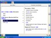
First, you select the PIDs you want to view, and in this case, I also needed the DTC status PID because that would be the PID triggering my recording. Once Datalogger is up, highlight the DTCCNT PID (or the PID you want to trigger off of) and go into this screen (hit the button under "#"):
Trigger setup: [IDS Triggering]
When you hit the "Autocapture" button, the options on the right of the screen will be displayed. If you select "Beep", IDS will activate a tone telling you a recording has been triggered. Hitting the "i" buttion will explain the difference between "Transition" & "Condition".
Since I had just cleared the DTCs, P1000 was in memory and the DTCCNT PID was recognizing that; so I had to set my upper limit to 1. If, while driving, the P1000 clears, you need to set the upper limit to 0.
Here's my recording time setup:
[IDS Triggering]
Unfortunately, the P0741 didn't return during the test drive so I had to induce a DTC for this example. This is what I got:
[IDS Triggering]
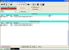
You can use any PID to trigger a recording and there are tons of different cases where this can be useful. Here's another example where I triggered a recording:
[2006 Ford F-250 Super Duty XL, ECM/Inputs/Outputs Scan Data]
In that case, nobody was around to watch the screen or wiggle the harness and I didn't feel like routing all that IDS cabling to the engine bay. I knew something happened when I heard the "Beep".
Maybe this will help someone.
How to Diagnose a Bad MAF Sensor in 10 Minutes
Technical Tips Forum
Matthew from Illinois
A few months ago this vehicle came in with the MIL on. I scanned it and this is what I found. [1999 Chevrolet Express 3500, Scan Data] [1999 Chevrolet Express 3500, Waveform] This van has a P0131 and a pending P0151; the code descriptors and definitions are important here. These are not circuit codes, they can be cause by a lean condition.
What next? Well, it's your first job of the day and you don't feel like getting your hands dirty until you're done eating your morning donut.
When it comes to freeze frame I really only trust LTFTs and ECT. Both banks are lean in the Freeze Frame and both banks are setting codes. This tells me I am diagnosing something that would make both banks go lean. For a lean condition there are 3 common problems that I can rule out quickly: vacuum leak, bad fuel pump and bad MAF.
A vacuum leak would cause a lean condition at idle and would be better around 2500 RPM.
A bad MAF sensor will tend to have positive fuel trims at load. This is why I recommend testing fuel trims at a steady cruise when testing a MAF. Fuel trims may also be negative at idle with a bad or dirty MAF.
Here is the data from our subject vehicle. Idle [1999 Chevrolet Express 3500, Scan Data] 2500 RPM [1999 Chevrolet Express 3500, Scan Data] Steady Cruise [1999 Chevrolet Express 3500, Scan Data]
VE (Volumetric Efficiency) is the measurement of how well an engine can pump air, remember an ICE engine is like a large air compressor. What I do is monitor MAF in g/s, RPM, and both upstream O2 sensors. I then take the vehicle on the road and take a recording of a WOT 1-2 shift. [1999 Chevrolet Express 3500, Scan Data] I then plug the information into my VE calculator. [1999 Chevrolet Express 3500, Photo]
Now that we have capture all of our data it's time to go back to the shop and analyze it. This engine's VE is 53% which is very low. On this particular engine I would hope to see more than 75%. Our fuel trims go positive at a steady cruise and negative at idle. Notice the O2 sensors also go lean. If this were a bad fuel pump we would have good VE with lean O2 sensors.
With all of this data combine I am ready to condemn the MAF. A new MAF is installed and I take the van back out for a VE test. Here are the results. [1999 Chevrolet Express 3500, Scan Data] [1999 Chevrolet Express 3500, Photo] This van is fixed. It was diagnosed without even popping the hood, and the only tool that was used was a lap top and scanner.
1998 Nissan Pathfinder 3.3L Intermittent No Start
Technical Tips Forum
Danny from California
Tip: Injectors do not operate while cranking, check the EGI (main) Relay.
A shop I occasionally deal with called and asked for direction on an intermittent no start on a Nissan Pathfinder. The tech asked how I would start diagnosing the problem. I told them that he should check scan data and make sure that nothing is grossly out of spec, such as TPS, Coolant Temps, RPM, or Injector Pulse Width. Just look for something usual. Make sure there's nothing going on with the security light. Check fuel pressure and volume. Check for spark. The tech said the vehicle had fuel pressure and spark, but no injector operation. I asked how they determined that and they said that the injectors were not clicking. He said he would check what I had suggested.
The tech drove the vehicle to my shop unannounced, and told me to take my time diagnosing the problem. I asked the tech if they checked scan data, and he said:
& nbsp;
"It has no codes."
I asked if he checked the TPS and Coolant Sensor values, and he said:
"They should be fine, we changed those parts".
I said, "We start with 1.5 hrs up front". "You can watch and help if you want while you wait for your ride". I hooked up my Solus Pro scanner and found none of the PIDs out of spec. I tried cranking the vehicle over, but it wouldn't start. I checked the #1 injector control circuit and I could see the PCM pulling the circuit to ground, but there is no spike when the driver turns off. I then dual traced the power and control circuit at the injector with my Vantage Pro, and this is what I saw.
[1998 Nissan Pathfinder LE, ECM/Inputs/Outputs Waveform]
Looking at Alldata, it shows that the EGI relay powers both the PCM and the Injectors. It's a 5 Pin relay, and apparently there are 2 switches/circuits within the relay to power the PCM and Injectors separately.
I took a #2 Phillips Dark Blue Snap On Screwdriver, (There is a difference) and used the handle to tap the top of the relay while the tech from the other shop cranked the engine over, this is what happened.
[1998 Nissan Pathfinder LE, ECM/Inputs/Outputs Waveform]
I told the tech he probably could have used a DMM and a test light to diagnose this problem. He said he used a "noid" light and it did flash dimly. He thought that the PCM could have been bad, but he didn't want to go there.
A hot test light on the control side would have resulted in a bright flashing light while cranking. If he used a grounded test light on the control side it would have resulted with a very dim or no light. At that point he could have monitored the "hot" side with either the test light or DMM. KOEO with the multimeter would have shown battery voltage, but connecting a test light to that circuit would have brought the voltage down. Then he could have looked in a wiring diagram as to where the power came from. Tapping the relay would have resulted in a bright test light. He said, & nbsp;
"Wouldn't it be easier just to change the relay instead of doing all that testing?"
Right, so I put up this tip.
Using Music to Understand CAN & Vise/Versa
Technical Theory Forum
Robby from Alabama
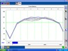
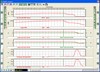
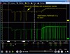
Over the past few months, there have been several very interesting threads on CAN that's really pegged my interest. CAN is an extremely reliable communication network. One reason is it's resistance to interference due to using the voltage differential between the High & Low CAN lines. Here is a MS CAN capture I took on an 08 F450 with no known issues:
[2008 Ford F-450 Super Duty XL, ECM/Inputs/Outputs Waveform]
In that capture, Channel 1 was on Pin 3 of the DLC and channel 2 was on Pin 11 of the DLC. My ground was a chassis ground, Pin 5. The purple trace is a math channel within PICO; Channel 1 voltage (-) Channel 2 voltage or the voltage differential. I thought it was very interesting how clean the signal is now.
Here is another capture I took with the Pos lead on Pin 3 & the Neg lead on Pin 11:
[2008 Ford F-450 Super Duty XL, ECM/Inputs/Outputs Waveform]
BTW, the tall peak at the end is an acknowledgement bit. The sending module with do a check sum for the data field. The receiving module(s) will also do a check sum and if the check sums agree, there will be a dominant "ACK" bit.
This is my theory about the very brief peaks at every rising edge. I believe this is the modules doing bit-by-bit monitoring. Each module will receive the data at virtually the same time. Each module is expecting a certain voltage level. If the modules receive the expected voltage level, they will bring the voltage down to the where it flattens off. The peak is also about 160 ns.
So where does the music come in. I love music. I deal with live sound with our church, I have an amateur recording setup, and I love to play. Today, I had some time to play around. Most everyone has seen an XLR cable (aka: microphone cable). This is a 3 conductor cable capable of carrying a balance signal. I couldn't wrap my head around what a balance signal was, so I asked someone about it a couple of years ago. He said a balanced signal is carrying 2 identical signals of the sound source, except one is 180 degrees out of phase. That way, any interference will be blocked out. That sounded pretty cool and smart, but then I learned things about CAN (mainly voltage differentials). The 180 degree thing started not to make sense.
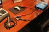
My feelings is that the other signal was not 180 out of phase, but simply inverted. I have a PICO, a dynamic microphone, and a dirt cheap XLR cable that I didn't care to cut up:
[Test leads hooked to a cut XLR cable]
[Test leads hooked to a cut XLR cable]
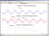
This is what I got.
[Test leads hooked to a cut XLR cable]
I got the pitch of A below middle C (which is 440 hz at standard pitch; aka A440) in my head and hummed it into the microphone. My frequency matched (I was on key!) and sure enough, the signal is inverted.
I thought this was very interesting, my wife wasn't as thrilled :)
BTW, some of the info on CAN came from this book:
http://www.amazon.com/Comprehensible-Guide-Controller-Area-Network/dp/0976511606 [amazon.com]
It's a very inexpensive book with tons of info on how CAN operates. It's not that bad of a read either. CAN is used in a ton of applications: aerospace, space craft, appliances, etc. One thing to keep in mind, SAE J2284 defines the CAN standard for automotive. Other applications have their own standards. All are designed/built off the CAN standard. There are differences in how each application does things. So if you read something about CIA (CAN in Automation), it my disagree with what you know about automotive CAN.
Feel free to correct anything here, I'm still learning. I hope we all can learn something here.
| |